
Cumulus Linux Data Centre Fabrics
Cumulus Linux: A Guide to L2 Data Centre Fabrics
In an era where infrastructure is code, some aspects of networking still feel like a black box? Proprietary networking platforms, such as Cisco's IOS, Juniper's...
In an era where infrastructure is code, some aspects of networking still feel like a black box? Proprietary networking platforms, such as Cisco’s IOS, Juniper’s Junos, etc have controlled the switch market. That closed grip on hardware and software created real vendor lock-in and inflated costs. I see Arista making a play with a Linux-based system, but let’s be honest, it still relies on their hardware. This changes when Cumulus Linux and the wider open-source networking ecosystem enter the chat. It’s a powerful approach that shatters the proprietary pattern, giving you freedom and control over your infrastructure.
The Linux Revolution in Networking
At its core, Cumulus Linux is a networking-focused operating system based on Debian, designed specifically for bare-metal network switches. Instead of a black box with a proprietary CLI, you get a full-fledged Linux distribution running on your network hardware. This is the Linux kernel doing the heavy lifting, allowing you to treat your switches like standard Linux servers. Your existing Linux scripting skills become direct network automation capabilities, drastically reducing the operational learning curve.
- Familiarity and Skill Transfer: Standard Linux commands, file structures, and tools apply directly to the switch.
- Automation at Scale: Because it is standard Debian, you can manage switches using Ansible, Puppet, or Python scripts, replacing manual CLI configuration with automated playbooks.
- Flexibility and Customization: You are not locked into proprietary vendor features. You can install Debian packages, run monitoring agents, and tailor telemetry directly.
Open Networking and ONIE: Disaggregated Hardware
The concept of Open Networking separates physical switch hardware from the network operating system. This disaggregation allows organizations to choose independent hardware and software platforms.
A critical enabler of open networking is the Open Network Install Environment (ONIE). Think of ONIE as the bootloader for bare-metal switches. It is a lightweight Linux environment pre-installed on ONIE-compliant hardware that discovers and installs compatible network operating systems over the network.
Declarative Configuration: The NVUE Object Model
While Cumulus Linux provides direct Linux shell access, it introduces a structured, object-oriented configuration framework called the NVIDIA User Experience (NVUE). NVUE acts as the declarative control plane and API for the switch. Instead of manually editing configuration files across /etc/network/interfaces and routing daemons, NVUE centralizes device state into a structured object model.
- You define the desired state for objects like
interfaceorrouter bgp. - NVUE verifies and applies the required system changes, minimizing configuration drift.
This declarative model supports predictable automation across the entire fabric.
Data Centre Topology: Understanding Clos Architecture
Modern data centres generate substantial east-west traffic between servers. The two-tier Clos architecture (spine-leaf) is designed specifically to handle this traffic pattern efficiently:
- Spine Layer: Provides non-blocking high-speed transit between leaf switches.
- Leaf Layer: Connects directly to compute hosts and storage nodes.
Every leaf connects to every spine, ensuring all traffic travels an equal number of hops. In pure Layer 3 fabrics with BGP, this delivers predictable latency and active-active Equal-Cost Multi-Path (ECMP) forwarding.
Your Lab, Your Playground: GNS3 Setup
To truly grasp Cumulus Linux open networking configuration , hands-on experience is paramount. We use GNS3 for risk-free experimentation. Our practice topology is a two-tier spine-leaf: S1 and S2 are the spines, and S3 and S4 are the leaves.
Our Practice Topology: A Two-Tier Clos in Action
The connections are specific:
- S3 connects to S1 (
swp1) and S2 (swp2). - S4 connects to S1 (
swp1) and S2 (swp2). - Endpoints (V10, V20, V30) connect to S3/S4 on
swp4,swp5, andswp6.
First Steps: Getting Our Hands Dirty
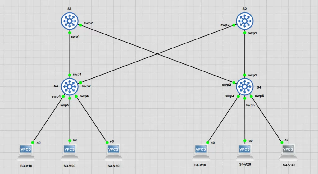
First, set your hostnames (e.g., nv set system hostname S1). The interfaces in Cumulus are named swp (switch port), followed by a number (e.g., swp1). After any change, always run nv config apply to push your changes to the active configuration, and then nv config save to write those changes to persistent memory. This two-step handshake is non-negotiable for engineers who value persistence.
VLAN Trunk & Access Port Configuration
In the Linux network world, Layer 2 operations like VLAN tagging are handled by a bridge , which acts like a virtual switch within the kernel. Unlike proprietary OSes, where the switch ASIC handles VLANs exclusively, Cumulus exposes this Linux abstraction. We will use the default VLAN-aware bridge , br_default.
Configuration on S3 (and identically on S4):
We assign the interfaces to the br_default domain:
nv set interface swp1-2,4-6 bridge domain br_defaultThen, configure the VLANs allowed on this domain (10, 20, 30):
nv set bridge domain br_default vlan 10,20,30Finally, set the access ports to their respective VLANs:
nv set interface swp5 bridge domain brdefault access 10
nv set interface swp4 bridge domain brdefault access 20
nv set interface swp6 bridge domain br_default access 30
Configuring the Spine Switches: S1 and S2
The spines must be configured as trunks to carry traffic for all required VLANs.
S1 and S2 Trunk Ports:
nv set bridge domain brdefault vlan 10,20,30
nv set interface swp1-2 bridge domain brdefault
Spanning Tree Protocol (STP): Preventing Layer 2 Loops
In any Layer 2 network with redundant paths, a broadcast storm will rapidly exhaust link bandwidth and crash switch control planes. Cumulus defaults to RSTP (IEEE 802.1w).
To define the spanning tree topology deterministically, we configure the STP priority so that S1 (lower priority value) operates as the primary root bridge and S2 serves as the secondary root bridge.
On S1, set the STP priority:
nv set bridge domain br_default stp priority 24576On S2, set the STP priority:
nv set bridge domain br_default stp priority 28672Enabling STP Port Admin Edge and BPDU Guard
For access ports connected directly to compute nodes or end devices, ports should transition to the forwarding state immediately without standard listening/learning delay. Cumulus provides STP Port Admin Edge (the open-networking equivalent of Cisco PortFast).
Under defense-in-depth design, if an unmanaged switch or rogue device is inadvertently connected to an edge access port, it could trigger a topology loop. Enabling BPDU Guard immediately disables any edge port that receives Spanning Tree BPDUs.
On S3 and S4, configure edge mode and BPDU guard on host-facing access ports (swp4-6):
nv set bridge domain br_default stp state up
nv set interface swp4-6 bridge domain br_default stp admin-edge on
nv set interface swp4-6 bridge domain br_default stp bpdu-guard on
Verifying Your Configuration
Before verifying, remember to apply and save your changes: nv config apply and nv config save.
After configuring STP, it’s always a good idea to verify the changes. While nv config showis the go-to for seeing the entire running configuration (just like show run), you can use more surgical commands for specific checks. These nv show commands are invaluable:
nv show bridge domain br_default: Gives a high-level summary of the bridge, its ports, and VLANs.nv show interface: Shows the status of all interfaces on the switch.nv show interface swp1: Dives deep into a single port, showing its bridge, VLAN, and STP details.
To view the overall STP state for the bridge domain:
nv show bridge domain brdefault stp state
nv show bridge domain brdefault stp
To see the STP state for a specific interface, like the trunk port swp1:
nv show interface swp1 bridge domain br_default stpFinally, to get a comprehensive view of all your running configurations, use the powerful nv config show command.
Verifying the L2 Fabric: Does It Ping?
Configuration is one thing; data plane verification is the moment of truth. Let’s prove our L2 fabric works as expected.
1. Configure VPC IPs (Confirmed)
We will use the confirmed IP addresses for our virtual PCs, ensuring they are all in the correct subnet for their respective VLANs.
- VLAN 10 (Subnet 192.168.10.0/24):
- On
S3-V10:ip 192.168.10.100/24 - On
S4-V10:ip 192.168.10.101/24
- On
- VLAN 20 (Subnet 192.168.20.0/24):
- On
S3-V20:ip 192.168.20.100/24 - On
S4-V20:ip 192.168.20.101/24
- On
- VLAN 30 (Subnet 192.168.30.0/24):
- On
S3-V30:ip 192.168.30.100/24 - On
S4-V30:ip 192.168.30.101/24
- On
2. Test 1: Intra-VLAN Connectivity (Success)
Let’s test connectivity between two hosts in the same VLAN but on different switches. This confirms that our VLAN-aware bridges and trunks are functioning correctly across the fabric.
FromS3-V10, ping S4-V10: ping 192.168.10.101
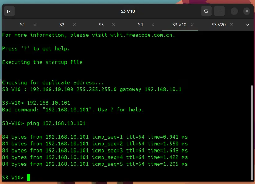
As you can see, the ping is successful. The packet travels from S3-V10 up to S3, across the trunk to a spine (S1 or S2), down to S4, and finally to S4-V10. Our L2 fabric is alive.
3. Test 2: Inter-VLAN Segmentation (Failure)
Now, let’s test our segmentation. A ping between two different VLANs (without a router) must fail. This proves our VLANs are properly isolated.
FromS3-V10, ping S3-V20: ping 192.168.20.100
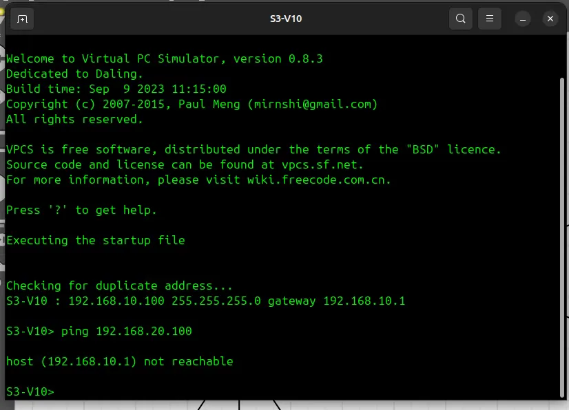
This ping fails as expected. S3-V10 is in VLAN 10, and S3-V20 is in VLAN 20. The switch correctly prevents traffic from crossing these L2 boundaries.
Conclusion: L2 Foundation Secured, L3 Awaits
This is where we’ll pause for now. You’ve successfully built and secured the crucial Layer 2 underpinnings of your modern data centre fabric. From assigning VLANs using the powerful NVUE object model to proactively preventing broadcast storms with an explicitly configured and protected STP topology, you have the necessary foundation.
But this is just the beginning. The real power of this Clos architecture is unleashed at Layer 3.
In Part 2 of this series, we will build on this foundation. The logical next step for this fabric is to move to Layer 3 and configure the routing protocols that make a Clos architecture so powerful. We’ll explore how to build a true, high-performance L3 fabric using BGP.
In a future article, we will tackle other critical data centre concepts, such as MLAG and Bonding, to build highly available connections to our endpoints.