
Cumulus Linux Data Centre Fabrics
Building a Resilient Multi-Vendor Data Centre Fabric: A Cumulus MLAG and VRR Deep Dive
I have been spending quite a bit of my time labing on different data centre design models, and let's just say it has been a really exciting journey
I have been spending quite a bit of my time labing on different data centre design models, and let’s just say it has been a really exciting journey. There is something satisfying about watching a complex topology come to life. I am eager to share this specific project because it perfectly illustrates the fundamentals of a modern Multi-Vendor Data Centre Fabric.
On paper, building a fabric is a beautiful, symmetrical dream. However, when you actually sit down at the terminal, the cables get plugged in, and suddenly, you are staring at an OSPF adjacency stuck in EXSTART because someone forgot to check the MTU. It happens to the best of us. And honestly, that is where the real learning starts.
I recently spent some time in the lab putting together a Layer-2/Layer-3 stretched fabric using Cumulus Linux and Cisco. It is a classic Leaf-Spine setup, but it includes a few real-world twists designed to test how these systems actually handle failure.
One thing I didn’t mention earlier is that we are not just looking for connectivity here. We are looking for true resilience. Therefore, if a cable dies or a switch loses power, the end-user should not even notice.
The Use Case: Who is this for?
I will be the first to admit that BGP EVPN-VXLAN is the popular choice right now. However, let us just say that for a small-to-medium enterprise or an isolated Pod in a larger facility, what we are building here is often the optimal choice.
It is possible that you are working in an environment with up to 20 racks, hosting VMware clusters or legacy bare-metal storage. Those systems still demand standard Layer 2 LACP bonds. In those specific cases, this setup provides high availability without the complexity of a full-blown overlay network.
For the Cisco veterans reading this, think of MLAG as the Cumulus equivalent of VPC (Virtual Port Channel). Think of MLAG like two bouncers coordinating at the entrance of a club. To the guests (our Cisco switches), they look like one unified checkpoint. Similarly, VRR is the Active-Active version of HSRP. If you have ever felt the sting of a standby HSRP router sitting idle while the primary is maxed out, you will quickly appreciate the “both-engines-running” approach of VRR.
Topology & IP Addressing Overview
Before we touch the CLI, we need a solid game plan. We have a multi-vendor stretched fabric.
- Spine Layer: Spine-1 and Spine-2. Their only job is the OSPF Area 0 underlay.
- Leaf Layer: Leaf-1 and Leaf-2 running Cumulus Linux. They act as a unified MLAG pair and the Active-Active VRR Gateway.
- Access Layer: BOND1-SW (Rack 1) and BOND2-SW (Rack 2) running Cisco IOSvL2, dual-homed to the Leaves.
Here is exactly how we laid out the physical IPs. Every Leaf connects to every Spine. You can also download the GN3 project file below and follow along.
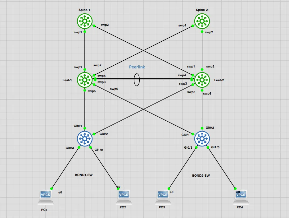
| Node | Interface | Connection | IP / Details |
|---|---|---|---|
| Spine-1 | lo | N/A | 8.8.8.8/32, 10.255.255.1/32 |
| Spine-2 | lo | N/A | 8.8.8.8/32, 10.255.255.2/32 |
| Spine-1 | swp1 / swp2 | Leaf-1 / Leaf-2 | 10.0.1.1/30 / 10.0.1.5/30 |
| Spine-2 | swp1 / swp2 | Leaf-1 / Leaf-2 | 10.0.2.1/30 / 10.0.2.5/30 |
| Leaf-1 | swp1 / swp2 | Spine-1 / Spine-2 | 10.0.1.2/30 / 10.0.2.2/30 |
| Leaf-2 | swp1 / swp2 | Spine-1 / Spine-2 | 10.0.1.6/30 / 10.0.2.6/30 |
| Leaves | vlan10 / 20 | VRR Gateway | 10.10.10.1/24 / 10.10.20.1/24 |
Let us take this strictly one switch at a time.
Step 1: The Core Underlay (Spine-1)
We start with Spine-1. Before we can route any traffic, we need to assign our base IP addresses. Notice how we assign 8.8.8.8 to a loopback. We are forcing this into OSPF to simulate an Internet edge route.
# Execute on Spine-1:
# 1. Base IP Addressing
nv set interface lo ip address 8.8.8.8/32
nv set interface lo ip address 10.255.255.1/32
nv set interface swp1 ip address 10.0.1.1/30
nv set interface swp2 ip address 10.0.1.5/30

# 2. Enable OSPF and set explicit Router ID
nv set vrf default router ospf enable on
nv set vrf default router ospf router-id 10.255.255.1

# 3. Add interfaces to OSPF Area 0
nv set interface lo router ospf area 0
nv set interface swp1 router ospf area 0
nv set interface swp2 router ospf area 0
nv config apply
Step 2: Redundancy at the Core (Spine-2)
Spine-2 looks almost identical to Spine-1. The primary differences are the unique physical IPs for the transit links and the Router ID (10.255.255.2). Because Spine-2 also advertises the 8.8.8.8 loopback, the Leaves will ultimately see two equal-cost paths to the “Internet.”
# Execute on Spine-2:
# 1. Base IP Addressing
nv set interface lo ip address 8.8.8.8/32
nv set interface lo ip address 10.255.255.2/32
nv set interface swp1 ip address 10.0.2.1/30
nv set interface swp2 ip address 10.0.2.5/30

# 2. Enable OSPF and set explicit Router ID
nv set vrf default router ospf enable on
nv set vrf default router ospf router-id 10.255.255.2

# 3. Add interfaces to OSPF Area 0
nv set interface lo router ospf area 0
nv set interface swp1 router ospf area 0
nv set interface swp2 router ospf area 0
nv config apply
The Concept: VRR + MLAG on Cumulus
Before we dump a wall of CLI commands for the Leaf switches, we need to talk about why we are doing this. Are VRR and MLAG together overkill?
Short answer? Yes. And not just reasonable, it is practically the canonical leaf-layer design on Cumulus Linux as I have seen so far. If anything, running one without the other in a dual-attached environment is the thing that should actually raise eyebrows. But here is why.
What Each Piece Is Actually Doing
MLAG bonds two physical Cumulus switches into a single logical LAG peer for downstream devices like your servers or firewalls. The two switches coordinate over a peerlink (A direct connection between the two MLAG switches) and share a system MAC, so the downstream device sees one logical switch.
VRR (Virtual Router Redundancy) is the answer to default gateway redundancy on SVIs. VRR is strictly active/active. Both MLAG peers advertise the same virtual IP and virtual MAC simultaneously on a given VLAN SVI. Both can route traffic. Neither is sitting idle waiting for the other to fail.
Why They Are Complementary
Think of it this way. MLAG solves your Layer 2 redundancy problem by eliminating blocked STP ports. VRR solves your Layer 3 gateway problem by dictating where the host sends traffic when it needs to leave the subnet.
If you use VRRP, which does not operate in active/active mode, instead of VRR, only one switch is actively routing. You have just wasted half your forwarding capacity and introduced asymmetry.
The Things You Actually Need to Get Right
This is where the nuance lives in a production environment:
- Peerlink sizing: Your peerlink carries MLAG keepalives, Broadcast traffic, and any traffic that lands on the “wrong” peer. Size it generously. At a minimum, use a 2x25G bond, but realistically aim for 2x100G in dense environments.
- ARP/ND synchronisation: Cumulus syncs ARP tables across MLAG peers automatically, but you need to verify this is working. If it breaks, one peer might route traffic it has no ARP entry for, causing unnecessary peerlink saturation.
- Routing on the fabric side: VRR handles the host-facing gateway. You still need a routing protocol northbound toward your spines. While BGP unnumbered is the most common pairing in the wild, OSPF (like we are using in this lab) handles ECMP naturally across both leaves.
- clagd health monitoring: If the MLAG daemon goes down on one peer, that peer should ideally lose its VRR participation too. Ensure your monitoring catches this fast.
Step 3: Building the Intelligence (Leaf-1)
Now that we understand the architectural intent, let us configure Leaf-1. First, we assign the physical transit IPs. Next, we build the MLAG bonds. Finally, we inject it all into OSPF.
# Execute on Leaf-1:

# 1. Base IP Addressing
nv set interface lo ip address 10.255.255.11/32
nv set interface swp1 ip address 10.0.1.2/30
nv set interface swp2 ip address 10.0.2.2/30

# 2. The MLAG Peerlink (The "Glue" between Leaves)
nv set interface peerlink bond member swp3,swp4

# 3. Global MLAG Setup
nv set mlag mac-address 44:38:39:BE:EF:AA
nv set mlag backup 10.255.255.12 vrf default # Heartbeat points to Leaf-2
nv set mlag peer-ip linklocal

# 4. Downstream Bonds (1 Unique MLAG ID per Cisco Switch)
nv set interface bond1 bond member swp5
nv set interface bond1 bond mlag id 1
nv set interface bond1 bridge domain brdefault

nv set interface bond2 bond member swp6
nv set interface bond2 bond mlag id 2
nv set interface bond2 bridge domain brdefault

# 5. VRR Virtual Gateways
nv set interface vlan10 address 10.10.10.2/24
nv set interface vlan10 address 10.10.10.1/24 virtual-router enable on
nv set interface vlan10 address 10.10.10.1/24 virtual-router mac-address 00:00:5e:00:01:01

nv set interface vlan20 address 10.20.20.2/24
nv set interface vlan20 address 10.20.20.1/24 virtual-router enable on
nv set interface vlan20 address 10.20.20.1/24 virtual-router mac-address 00:00:5e:00:01:02

# 6. OSPF Transit & Subnet Injection
nv set vrf default router ospf enable on
nv set vrf default router ospf router-id 10.255.255.11
nv set interface lo router ospf area 0
nv set interface swp1 router ospf area 0
nv set interface swp2 router ospf area 0
nv set interface vlan10 router ospf area 0
nv set interface vlan10 router ospf passive on
nv set interface vlan20 router ospf area 0
nv set interface vlan20 router ospf passive on
nv config apply
The Tutor’s Warning: Look closely at section 6. We are applying OSPF to vlan10. Cumulus VRR creates a hidden macvlan child interface in the background to handle the anycast IP. You must not apply OSPF to that hidden interface. If you do, OSPF will get incredibly confused. Only apply it to the parent physical interface, and always use passive on so you do not form rogue adjacencies with your servers.
Step 4: Completing the Pair (Leaf-2)
Leaf-2 mirrors Leaf-1, but you must pay attention to the subtle differences in IP assignments. Crucially, notice that the bond mlag id commands are identical to Leaf-1. Bond 1 gets ID 1. Bond 2 gets ID 2. This is exactly how the two independent switches coordinate to trick the Cisco access switches.
# Execute on Leaf-2:

# 1. Base IP Addressing
nv set interface lo ip address 10.255.255.12/32 # <-- Notice the .12 Router ID
nv set interface swp1 ip address 10.0.1.6/30 # <-- Unique transit IP
nv set interface swp2 ip address 10.0.2.6/30 # <-- Unique transit IP

# 2. The MLAG Peerlink
nv set interface peerlink bond member swp3,swp4

# 3. Global MLAG Setup
nv set mlag mac-address 44:38:39:BE:EF:AA
nv set mlag backup 10.255.255.11 vrf default # <-- Heartbeat points back to Leaf-1 (.11)
nv set mlag peer-ip linklocal

# 4. Downstream Bonds (Matching the IDs from Leaf-1)
nv set interface bond1 bond member swp5
nv set interface bond1 bond mlag id 1
nv set interface bond1 bridge domain brdefault

nv set interface bond2 bond member swp6
nv set interface bond2 bond mlag id 2
nv set interface bond2 bridge domain brdefault

# 5. VRR Virtual Gateways
nv set interface vlan10 address 10.10.10.3/24 # <-- Unique physical IP (.3 instead of .2)
nv set interface vlan10 address 10.10.10.1/24 virtual-router enable on
nv set interface vlan10 address 10.10.10.1/24 virtual-router mac-address 00:00:5e:00:01:01

nv set interface vlan20 address 10.20.20.3/24 # <-- Unique physical IP (.3 instead of .2)
nv set interface vlan20 address 10.20.20.1/24 virtual-router enable on
nv set interface vlan20 address 10.20.20.1/24 virtual-router mac-address 00:00:5e:00:01:02

# 6. OSPF Transit & Subnet Injection
nv set vrf default router ospf enable on
nv set vrf default router ospf router-id 10.255.255.12 # <-- Matches new Router ID
nv set interface lo router ospf area 0
nv set interface swp1 router ospf area 0
nv set interface swp2 router ospf area 0
nv set interface vlan10 router ospf area 0
nv set interface vlan10 router ospf passive on
nv set interface vlan20 router ospf area 0
nv set interface vlan20 router ospf passive on
nv config apply
Step 5: The Access Layer (Cisco BOND1-SW)
Now we connect Rack 1. On the Cisco side, we need to bundle our uplinks (Gi0/1 and Gi0/2) into a Port-channel. It is possible that you might know this by another name. While Cisco calls it a Port-channel, Cumulus and most Linux-based switches refer to it as a LAG or an LACP bond. Let us just say that regardless of the naming convention, any device connecting downstream to our MLAG setup must be configured to use LACP. We also need to configure the downstream access ports (Gi0/3 and Gi1/0) where our actual servers reside.
! Execute on BOND1-SW (Rack 1):
! MLAG Uplinks
interface range Gi0/1 - 2
 channel-group 1 mode active
!
interface Port-channel 1
 switchport trunk encapsulation dot1q
 switchport mode trunk
 switchport trunk allowed vlan 10,20
 lacp fast-switchover
 spanning-tree portfast edge trunk
!
! Downstream Access Ports (VPCS)
interface GigabitEthernet0/3
 switchport access vlan 10
 switchport mode access
 spanning-tree portfast edge
!
interface GigabitEthernet1/0
 switchport access vlan 20
 switchport mode access
 spanning-tree portfast edge
Notice the command spanning-tree portfast edge trunk under Port-channel 1. This tells the Cisco switch to bypass the standard 30-second Spanning Tree listening and learning phases.
A quick word of caution: In a production data centre, you should be extremely careful applying this to a switch-to-switch link. We are using it here as a ‘Lab Hack’ to achieve instant failover. Let’s just say that if you accidentally create a loop with this enabled, you’ll be dealing with a severe, facility-wide broadcast storm.
Step 6: The A/B Testing Control (Cisco BOND2-SW)
For Rack 2, we deliberately configure the switch differently. We are leaving out the STP optimisations on the uplink so we can visually observe the difference during a failure scenario later.
! Execute on BOND2-SW (Rack 2):
! MLAG Uplinks
interface range Gi0/1 - 2
 channel-group 1 mode active
!
interface Port-channel 1
 switchport trunk encapsulation dot1q
 switchport mode trunk
 switchport trunk allowed vlan 10,20
 lacp fast-switchover
! Notice: No spanning-tree portfast edge trunk here!
!
! Downstream Access Ports (VPCS)
interface GigabitEthernet0/3
 switchport access vlan 10
 switchport mode access
 spanning-tree portfast edge
!
interface GigabitEthernet1/0
 switchport access vlan 20
 switchport mode access
 spanning-tree portfast edge
Key Lab Lessons & Troubleshooting
If you are following along in your own lab, you will inevitably hit a few roadblocks. Here are the issues I fought through so you do not have to struggle.
- The MTU Mismatch Danger: Cumulus defaults interfaces to (Jumbo frames). Cisco IOS defaults to . If you leave this alone, well, it is highly likely you will spend hours wondering why LLDP is complaining, Cisco is flagging the EtherChannel as ‘inconsistent’, and OSPF is permanently stuck in
EXSTART. Therefore, you must hardcodemtu 1500on the Cumulus bonds facing the Cisco switches. - LACP Timer Mismatch: Cumulus wants to talk fast with 1-second LACP timers. Cisco defaults to a slow 30 seconds. If you do not apply
lacp fast-switchoveron the Cisco Port-channel, your ports will sit in a suspended(s)state after a link flap. - LACP System ID Mismatch: If the Cumulus MLAG peerlink completely breaks, Leaf-1 and Leaf-2 revert to being standalone switches. They will start sending different LACP MAC addresses down to the Cisco switch. Consequently, the Cisco switch will promptly suspend one of the uplinks to protect itself.
- NVUE 5.4 Syntax Changes: If you are trying to view the routing table in Cumulus 5.4, the old
nv show router routingcommand has changed. You now need to usenv show vrf default router rib ipv4 route.
Chaos Engineering Validation (The Tests)
We didn’t just build this to look at green lights. We intentionally broke the fabric to validate our design.
Chaos Test 1: L2 Access Uplink Failure We pulled one of the physical cables (Gi0/1) between the Cisco Access switch and Cumulus Leaf-1.
- Result on BOND1-SW (Optimised): We saw a near-instantaneous failover to Leaf-2 with minimal packet loss. This was entirely thanks to the ‘
portfast edge trunkandlacp fast-switchover’ commands. - Result on BOND2-SW (Standard): We experienced a -second traffic black hole. Spanning Tree painstakingly progressed through its Listening and Learning phases. Let us just say this proves exactly why timer mechanics matter.
Chaos Test 2: L3 Core Underlay Failure. We suspended the /30 transit link between Leaf-1 and Spine-1.
- Result: FRRouting instantly removed Spine-1 from the routing table. Because we designed an ECMP underlay, Leaf-1 simply shifted 100% of its North-South traffic to Spine-2 seamlessly.
Chaos Test 3: The Split-Brain Meltdown. We suspended both peerlink cables (swp3 and swp4) simultaneously.
- Result: This is where the
mlag backupHeartbeat saved us. Leaf-2 (the Secondary role) checked the heartbeat over the OSPF core, realised Leaf-1 was still alive, and gracefully shut down its own downstream bonds. The Cisco switch detected the link loss and forced all traffic through Leaf-1. This ensured a stable, loop-free topology.
Verification: The “Show” Commands
When you build this, you need to verify it. We used three different CLI paradigms during the lab.
NVUE (Declarative):
nv show mlag: The single most important command to verify peerlink health and the backup heartbeat.nv show interface bond1: Checks operational state, MTU, and LACP members.
FRRouting / vtysh (The Cisco-Like Fallback): When in doubt, drop into the native routing daemon.
- sudo
vtysh -c "show ip route": The classic way to view the routing table. It clearly displays the ECMP multipath routes to . - sudo
vtysh -c "show ip ospf neighbor": Verifies your adjacencies with the Spines.
Cumulus Linux Native:
clagctl: The classic, highly-detailed MLAG status command. It gives you a clean table showing system MACs, roles, and port states.
Cisco IOSvL2:
show etherchannel summary: Look for the(P)flag indicating the port is successfully bundled. If you see(s), check your MTU or LACP timers.show lacp neighbor: Essential for diagnosing System ID mismatches during a split-brain scenario.
Final Thoughts
Building a modern Multi-Vendor Data Centre Fabric is about balancing the need for raw routing speed with the gritty reality of physical failures. It requires a deep understanding of how different platforms, like Cumulus Linux and Cisco IOS, interpret standard protocols differently.
Hopefully, walking through this lab switch-by-switch helps you avoid the traps we encountered. Feel free to reach out if you are deploying something similar in your own environment!