

Imagine you’ve built a sleek, high-performance network, only for a single router or switch to fail and bring the entire thing down. The silence is deafening. As network engineers, that’s not just a bad day; it’s a catastrophic design flaw. Building networks that don’t crumble under pressure should be the standard.
In building a resilient network with redundancy across multiple switches and routers. This is where protocols like HSRP on your Layer 3 and STP on your Layer 2 links become your key players.
HSRP ensures your users default gateway never fails. While STP intelligently blocks redundant Layer 2 paths to stop broadcast storms, only unlocking them when a primary link fails.
Now, combine these protocols with a dynamic routing protocol, and you extend that redundancy across multiple networks. While HSRP and STP handle local traffic within an area, a dynamic routing protocol ensures the wider network is always aware of the best routes, even when things go sideways. This article is not about OSPF here, but I have a whole article dedicated to it.
To help you follow along, this guide provides the core configuration commands. The GNS3 and Packet Tracer files for this topology are available for download. You may need to modify some commands to match your specific setup, and that’s perfectly fine. The principles remain the same.
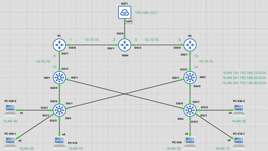
1. Our Network Map: The IP Addressing Scheme
Before we dive into the configurations, it is crucial to understand the IP addressing scheme for this topology. This map will guide you through the connections between the routers and switches, ensuring you can replicate the setup accurately in your lab.
Route Links Network
- Link 1:
10.10.10.0/30(Host –10.10.10.1–10.10.10.2) (Broadcast =10.10.10.3) = WAN – R1 - Link 2:
10.10.10.4/30(Host –10.10.10.5–10.10.10.6) (Broadcast –10.10.10.7) = WAN – R2 - Link 3:
10.10.10.8/30(Host –10.10.10.9–10.10.10.10) (Broadcast –10.10.10.11) = R1 – SW1 - Link 4:
10.10.10.12/30(Host –10.10.10.13–10.10.10.14) (Broadcast –10.10.10.15) = R2 – SW2
Switch VLAN and HSRP Configurations
- VLAN 10:
192.168.10.0/24 - VLAN 20:
192.168.20.0/24 - VLAN 30:
192.168.30.0/24
2. First-Hop Redundancy with HSRP
Let’s start with the Layer 3 switches, SW1 and SW2. These are the gateway for your VLANs, but what happens if one of them fails? That’s where HSRP comes in. HSRP( Hot Standby Router Protocol) is a Cisco proprietary protocol. Other vendors typically use VRRP (Virtual Router Redundancy Protocol) or GLBP (Gateway Load Balancing Protocol).
HSRP ensures that if one of your gateways goes offline, the other takes over with zero disruption to your end-users. You configure a single virtual IP address and MAC address for the standby group. One switch becomes the active router, and the other remains in a standby state. Imagine a PC in VLAN 10 trying to reach the internet. Without HSRP, if the default gateway (SW1’s IP) goes down, that PC is stuck. With HSRP, the standby switch (SW2) immediately becomes active, and traffic continues flowing. It’s a simple yet powerful design that keeps the packets moving.
SW1 Configuration
You first need to configure your preferred interface trunk to allow all VLAN to this switch and then configure the IP address to the interface connected or participating in Layer 3 routing to the router.
Follow the commands below for your setup. Note you can use your preferred interfaces as you desire.
Trunks are configured on interfaces GigabitEthernet0/0 and GigabitEthernet0/1 to carry traffic for multiple VLANs (10, 20, 30) to other switches or routers.
configure terminal
interface GigabitEthernet0/0
 switchport trunk encapsulation dot1q
 switchport mode trunk
 switchport trunk allowed vlan 10,20,30
exit
interface GigabitEthernet0/1
 switchport trunk encapsulation dot1q
 switchport mode trunk
 switchport trunk allowed vlan 10,20,30
exit
Interface GigabitEthernet3/3 is configured as a routed port (Layer 3 interface) to connect to another router or Layer 3 device. The no switchport command makes it act like a router interface.
configure terminal
interface GigabitEthernet3/3
 no switchport
 ip address 10.10.10.10 255.255.255.252
exit
For Spanning-Tree Protocol (STP) configuration, SW1 runs Rapid PVST+ and acts as the primary root bridge. And SW2 is configured for Rapid PVST+ but with a lower priority. Consequently, if SW1 fails, SW2 immediately takes over as the root bridge.
We set the spanning-tree mode to rapid-pvst and adjusted the path cost method to long to ensure consistent behaviour across both switches. This strategic configuration forces SW2 to operate as the backup, guaranteeing seamless failover and maintaining network stability.
configure terminal
spanning-tree mode rapid-pvst
spanning-tree pathcost method long
exit
To make this switch the root bridge, we set its Spanning Tree Protocol (STP) priority to 24576 for all VLANs.
configure terminal
spanning-tree vlan 1,10,20,30 priority 24576
exitSpecifically, we configure HSRP on the Switch Virtual Interfaces (SVIs) for the VLANs to provide a reliable default gateway for our hosts.
First, create and configure the SVI, assign its real IP address, and then enable HSRP Version 2 within its configuration mode.
Next, define the HSRP group and its virtual IP address, which serves as the default gateway. Adjust the priority to influence the active/standby election. The default priority is 100, so a higher value like 200 ensures this switch becomes the active router for the group.
Object Tracking and IP SLA (GNS3 Only)
For GNS3 users, you can add a more intelligent failover mechanism using IP SLA to track the reachability of your upstream router. If the router becomes unreachable, HSRP’s priority will automatically decrease, forcing a failover.
ip sla 10
 icmp-echo 10.10.10.9 source-interface GigabitEthernet3/3
 frequency 5
ip sla schedule 10 life forever start-time now
track 10 ip sla 10 reachability
VLAN 10 Configuration (Active for HSRP Group 1):
configure terminal
interface Vlan10
 ip address 192.168.10.1 255.255.255.0
 standby version 2
 standby 1 ip 192.168.10.3
 standby 1 priority 200
 standby 1 track 10 decrement 110
exit
VLAN 20 Configuration (Standby for HSRP Group 1):
configure terminal
interface Vlan20
 ip address 192.168.20.1 255.255.255.0
 standby version 2
 standby 1 ip 192.168.20.3
exit
VLAN 30 Configuration (Active for HSRP Group 3):
configure terminal
interface Vlan30
 ip address 192.168.30.1 255.255.255.0
 standby version 2
 standby 3 ip 192.168.30.3
 standby 3 priority 200
 standby 3 track 10 decrement 110
exit
Note: The use of standby 1 for VLANs 10 and 20 but standby 3 for VLAN 30 is a design choice often used to load balance traffic across two different switches acting as the active router for different VLANs.
SW2 Configuration
This configuration for SW2 provides essential redundancy and load sharing for the network.
Like SW1, we configured trunks on both GigabitEthernet0/0 and GigabitEthernet0/1 to carry the same VLANs 10, 20, and 30. This setup creates a consistent and loop-free topology across both switches, guaranteeing your network stays up and running, no matter what.
configure terminal
interface GigabitEthernet0/0
 switchport mode trunk
 switchport trunk encapsulation dot1q
 switchport trunk allowed vlan 10,20,30
exit
interface GigabitEthernet0/1
 switchport mode trunk
 switchport trunk encapsulation dot1q
 switchport trunk allowed vlan 10,20,30
exit
We configured Interface GigabitEthernet3/3 as a routed, Layer 3 port. We did this to connect the device directly to the wider network, allowing it to route traffic without relying on a VLAN.
configure terminal
interface GigabitEthernet3/3
 no switchport
 ip address 10.10.10.14 255.255.255.252
exit
SW2 is also configured with Rapid PVST+, but we’ve given it a lower priority than SW1. Consequently, we’ve designated SW2 as the backup root bridge for all VLANs. This ensures a seamless fail over, and if SW1 ever fails, SW2 takes over instantly.
configure terminal
spanning-tree mode rapid-pvst
spanning-tree pathcost method long
exit
A priority of 28672 is set for all VLAN on this switch. This is worse (higher) than SW1’s priority of 24576, ensuring SW2 is the backup root.
configure terminal
spanning-tree vlan 1,10,20,30 priority 28672
exit
HSRP is configured on the SVIs to provide gateway redundancy. Configure the HSRP group and its virtual IP address (must match the group IP on SW1).
You also need to configure the same IP SLA and tracking mechanism, but this time, it monitors the upstream link to R2.
ip sla 10
 icmp-echo 10.10.10.13 source-interface GigabitEthernet3/3
 frequency 5
ip sla schedule 10 life forever start-time now
track 10 ip sla 10 reachability
VLAN 10 Configuration (Standby for HSRP Group 1):
configure terminal
interface Vlan10
 ip address 192.168.10.2 255.255.255.0
 standby version 2
 standby 1 ip 192.168.10.3
exit
No priority is set, so it uses the default of 100. Since SW1 has a priority of 200 for this group, SW2 will be the standby router.
VLAN 20 Configuration (Active for HSRP Group 1):
configure terminal
interface Vlan20
 ip address 192.168.20.2 255.255.255.0
 standby version 2
 standby 1 ip 192.168.20.3
 standby 1 priority 200
 standby 1 track 10 decrement 110
exit
SW2 has a higher priority (200) for VLAN 20, making it the active router. SW1, with its default priority of 100 for this VLAN, will be the standby.
VLAN 30 Configuration (Standby for HSRP Group 3):
configure terminal
interface Vlan30
 ip address 192.168.30.2 255.255.255.0
 standby version 2
 standby 3 ip 192.168.30.3
exit
No priority is set (default 100). Since SW1 has a priority of 200 for group 3, SW2 will be the standby router.
3. Understanding HSRP Priority, Preempt, and Versions
While the commands might seem straightforward, the real magic is in the logic behind them. Let’s break down a few key HSRP concepts that give you control over your network’s behavior.
HSRP Priority and Election
Every HSRP group has a priority number from 0 to 255. The switch with the highest priority number becomes the active router, while the next highest becomes the standby. The default priority is 100. In our configuration, we intentionally set the priorities higher than the default on both switches to ensure the election is predictable and not left to chance based on which switch boots first.
The Preempt Command
The standby preempt command is a powerful tool. When enabled, it allows a router with a higher HSRP priority to immediately take over the active role from a lower-priority router. For example, if your primary switch (SW1) fails and the backup (SW2) takes over, once SW1 comes back online, it will automatically reclaim its active role because its priority is higher.
However, this command is not always the best choice. In a scenario where a switch is constantly flapping or rebooting, the preempt command would cause the active role to switch back and forth constantly. This leads to instability and unnecessary network churn. In a homogeneous network like this, where both SW1 and SW2 are identical models, there is no performance difference between them. You can live without preempt and avoid the “yo-yo effect” that would cause unnecessary state changes.
But, if your primary switch is a beast of a machine with a much higher throughput capacity, and your standby is an older, lower-spec device, you’d absolutely want to use preempt. In that case, you want the high-capacity device to handle the traffic as soon as it’s available, so you get the best performance. The trade-off is worth it.
Standby Version 2
The standby version 2 The command is just about the housekeeping. It’s an upgrade to the older HSRP version 1. With version 2, you get a wider range of group numbers (0−4095) and the ability to use a virtual MAC address that is no longer tied to a vendor-specific MAC block. This provides better compatibility and flexibility in multi-vendor environments. You should always use HSRP version 2 for new deployments.
4. The Loop-Free Foundation: STP Configuration
Consider the physical connections between SW1, SW2, SW3, and SW4. The redundant links are great for fault tolerance, but they create a problem: a loop. A Layer 2 loop will cause broadcast storms, bringing your network to its knees faster than a last-minute flight booking. This is where STP saves the day.
While the core concept of STP is defined by the IEEE 802.1D standard, the protocol we use here, PVST+ (Per-VLAN Spanning Tree Plus), is another Cisco proprietary protocol. This is a critical distinction because PVST+ maintains a separate spanning tree instance for each VLAN, allowing for load balancing. Other vendors, or even just the standard, rely on RSTP (Rapid Spanning Tree Protocol) and MSTP (Multiple Spanning Tree Protocol) to achieve similar goals with faster convergence times. The key here is to tune your STP to be fast and deterministic, ensuring a quick recovery.
STP is a protocol that runs on all your Layer 2 switches to intelligently block redundant paths, creating a single, loop-free topology. It designates one switch as the root bridge, and then calculates the best path to the root for every other switch. The redundant links are then placed in a blocking state. It’s like a traffic warden telling certain cars to wait so the entire road doesn’t become a parking lot. When a primary link fails, STP re-calculates the topology and unblocks a previously redundant link, restoring connectivity. Have you considered using Rapid Spanning Tree Protocol (RSTP) or Multiple Spanning Tree Protocol (MSTP) for faster convergence times?
Taking Control: STP Priority and Root Election
A switch becomes the root bridge based on two criteria: the lowest STP priority and the lowest MAC address. If you don’t manually set the priority, all your switches will have the default value of 32768. The election then becomes a lottery based on the MAC address. You don’t want a random switch becoming your root bridge because it happens to have the “luckiest” MAC address. That’s a bad design. You need to tell your network which switch should lead the show.
The STP priority is a 16-bit number that is configured in increments of 4096. While you can manually set it using the spanning-tree vlan X priority Y command, there’s a much more elegant way to do it.
Using “root primary” and “root secondary“
Cisco gave us some magic commands to simplify this. Instead of remembering the priority numbers, you can just use root primary and root secondary.
spanning-tree vlan [vlan-range] root primary: This command sets the priority to 24576, making this switch the preferred root bridge for the specified VLAN(s). It’s a quick and clean way to say, “You’re the boss.”spanning-tree vlan [vlan-range] root secondary: This command sets the priority to 28672. This makes the switch the backup root bridge. If the primary root bridge fails, this switch will take over. It’s your network’s contingency plan.
Using these commands ensures that the most capable or centrally located switch becomes the root bridge, providing a predictable and efficient path for all your traffic. You are in control, not the random MAC address.
5. Enhancing Redundancy with IP SLA and Object Tracking
We need to describe what we did with the SLA and object track commands and how it also helped is in ensuinging rediendancy. For the topology, we can see that SW1 and SW1 only have way gateway to out of ecah of then on interface g3/3 interface to RI and R2 respectively.
This means that of R1 could mean reachability probelms for VLAN routing though SW1 and dito problems for SW2. For the GNS3 users we were able to fix this polem using object tracking. The SLA track ICMP reachability to RI and R2 from SW1 and SW2 respectively and if there is failure, stanby using this information to decrese the priority forcing the default route to switch. esuring the faulire of R1 or R2 dosent mean downtime.
Unfortuanlty i coundnt relaicate this with packet tracer but in a life enviroment with the right kind of Layer3 switches and router objectr tracking works also.
6. Configuring the Access Layer: SW3 and SW4
Now, let’s talk about the switches at the end of the line: SW3 and SW4. Unlike SW1 and SW2, these are typically Layer 2-only switches and don’t require the complex routing or HSRP configurations. They are the access layer of your network, connecting end devices like computers, printers, and servers to the rest of the infrastructure. Their main job is to assign each device’s port to the correct VLAN. It’s a straightforward but critical task.
The configuration for these switches is minimal and focused. You simply need to set the ports that connect to your end devices to access mode and assign them to the appropriate VLAN. It’s about efficiency and keeping things simple where they can be.
Here’s a basic example of how you would configure a port for a device in VLAN 10. You will repeat this for each of your endpoints, assigning them to VLANs 10, 20, or 30 as needed.
SW3 & SW4 Access Port Configuration
configure terminal
interface FastEthernet0/1
 description PC in VLAN 10
 switchport mode access
 switchport access vlan 10
exit
7. Configuring the Routers: Dynamic Routing with OSPF and NAT
Now, let’s move up the chain to the routers, R1, R2, and the WAN router. They’re the traffic cops of this network, making sure packets get to where they need to go, both within the local network and out to the internet. Unlike the Layer 3 switches, which require the no switchport command to become a routed interface, routers are Layer 3 devices by default. You just need to configure the IP addresses on the interfaces and define your routing protocols.
Router Roles in OSPF
This is where the two-area OSPF comes in. You’ve got a single OSPF domain, but it’s logically separated into a backbone area (Area 0) and a standard area (Area 1).
- Autonomous System Boundary Router (ASBR): The WAN router is your ASBR. It’s the gateway to the outside world, connecting your OSPF domain to an external network like the internet.
- Area Border Routers (ABRs): R1 and R2 are your ABRs. They connect the backbone area (Area 0) to the standard area (Area 1). They manage the flow of routing information between the two areas, keeping the routing tables in Area 1 smaller and more efficient.
Router and Switch Configurations
Here are the configurations for each of the routers and the relevant switch configs, including the WAN router’s configuration you provided, with a few crucial points on OSPF and NAT.
WAN Router Configuration (ASBR)
The WAN router’s job is to connect your network to the internet. It acts as an ASBR by advertising a default route (0.0.0.0) to the entire OSPF domain, telling all other routers where to send traffic for the internet. It also handles NAT to translate the private IP addresses of your internal network to a public IP address, allowing multiple devices to share a single internet connection.
configure terminal
interface GigabitEthernet0/0
 ip address dhcp
 duplex auto
 speed auto
 media-type rj45
 ip nat outside
 exit

interface GigabitEthernet0/1
 ip address 10.10.10.1 255.255.255.252
 duplex auto
 speed auto
 media-type rj45
 ip nat inside
 exit

interface GigabitEthernet0/2
 ip address 10.10.10.5 255.255.255.252
 duplex auto
 speed auto
 media-type rj45
 ip nat inside
 exit


router ospf 1
 router-id 5.5.5.5
 network 10.10.10.0 0.0.0.15 area 0
 network 192.168.10.0 0.0.0.255 area 1
 network 192.168.20.0 0.0.0.255 area 1
 network 192.168.30.0 0.0.0.255 area 1
 default-information originate always
 exit

! Static Route for Internet Connectivity
ip route 0.0.0.0 0.0.0.0 192.168.122.1

! NAT Configuration
ip nat inside source list 1 interface GigabitEthernet0/0 overload

! Access List to Define Internal Networks for NAT
access-list 1 permit 192.168.10.0 0.0.0.255
access-list 1 permit 192.168.20.0 0.0.0.255
access-list 1 permit 192.168.30.0 0.0.0.255
access-list 1 permit 10.10.10.0 0.0.0.252
exit
The default-information originate always command tells the WAN router to always advertise a default route into the OSPF domain, regardless of whether a default route is present in its own routing table. This is how the internal network knows to send all internet-bound traffic to the WAN router.
R1 Configuration
This router connects the WAN to the switches. It operates as an ABR, connecting Area 0 to Area 1.
configure terminal
interface GigabitEthernet0/0
 ip address 10.10.10.2 255.255.255.252
 no shutdown
exit
interface GigabitEthernet0/1
 ip address 10.10.10.9 255.255.255.252
 no shutdown
exit
router ospf 1
 router-id 4.4.4.4
 network 10.10.10.0 0.0.0.15 area 0
 network 192.168.10.0 0.0.0.255 area 1
 network 192.168.20.0 0.0.0.255 area 1
 network 192.168.30.0 0.0.0.255 area 1
exit
R2 Configuration
Just like R1, R2 connects the WAN to the switches and operates as an ABR, connecting Area 0 to Area 1.
configure terminal
interface GigabitEthernet0/0
 ip address 10.10.10.6 255.255.255.252
 no shutdown
exit
interface GigabitEthernet0/1
 ip address 10.10.10.13 255.255.255.252
 no shutdown
exit
router ospf 1
 router-id 3.3.3.3
 network 10.10.10.0 0.0.0.15 area 0
 network 192.168.10.0 0.0.0.255 area 1
 network 192.168.20.0 0.0.0.255 area 1
 network 192.168.30.0 0.0.0.255 area 1
exit
SW1 OSPF Configuration
SW1 is a router within Area 1.
configure terminal
router ospf 1
 router-id 2.2.2.2
 network 10.10.10.8 0.0.0.3 area 1
 network 192.168.10.0 0.0.0.255 area 1
 network 192.168.20.0 0.0.0.255 area 1
 network 192.168.30.0 0.0.0.255 area 1
exit
SW2 OSPF Configuration
SW2 is a router within Area 1.
configure terminal
router ospf 1
 router-id 1.1.1.1
 network 10.10.10.0 0.0.0.15 area 0
 network 192.168.10.0 0.0.0.255 area 1
 network 192.168.20.0 0.0.0.255 area 1
 network 192.168.30.0 0.0.0.255 area 1
exit
8. Testings
So, you’ve done all the work. Now, how do you know it paid off? Testing this setup is straightforward using ICMP.
From any host (VPC) on your network, you should be able to ping your default gateway, which is one of the .3 IPs you configured for your VLANs.
If your setup is correct, you should be able to ping anywhere within your network topology. Try pinging a device in a different VLAN, or a router interface, or even a host on the other side of the network. If the pings are a success, you know your HSRP and OSPF are doing their jobs.
For my GNS3 users, don’t stop there. Go one step further and see if you can ping a public IP address like 8.8.8.8 or even 1.1.1.1. If that works, your NAT and default route are on lock.
The ultimate test, however, is to simulate a failure. Try turning off a switch to see how the network responds. Don’t worry, it’s not a bug; it’s a feature! The network should automatically reroute traffic, and your ping should only drop a few packets before it resumes. This is the true proof that your no-single-point-of-failure design is working as it should.
9. Conclusion
Building a resilient network is a case of careful design and hands-on implementation. By leveraging technologies like HSRP for first-hop redundancy, STP for loop prevention, and OSPF for dynamic and efficient routing, you’ve now created a network that can handle the inevitable challenges of downtime and failure. Your network is the lifeblood of your organization, ensuring its stability is a core business imperative.
Leave a Reply