
Building a Site-to-Site IPsec VPN: A Practical Lab Guide
Introduction: Why Do We Need VPNs? The internet is fundamentally a wild, untrusted place
Introduction: Why Do We Need VPNs?
The internet is fundamentally a wild, untrusted place. When a business needs to connect two remote offices, sending internal data over the public web is incredibly risky. Consequently, network engineers use Virtual Private Networks. Think of the public internet as a chaotic public highway. A VPN is basically an armoured truck driving on that highway. Anyone can see the truck, but absolutely nobody can see the cash inside.
For enterprise environments, we often rely on IPsec. It operates transparently at the network layer, making it invisible to the users and applications generating the traffic. Today, I will walk you through configuring a site-to-site IPsec VPN on pfSense. I built this lab recently to see exactly what an encrypted packet looks like on the wire and how it compares to an unencrypted packet traversing the same path.
The Lab Topology
Before we touch the firewalls, we must build the “highway.” In this lab, we have two pfSense firewalls acting as the security edge for two different sites: California and New Jersey. However, instead of connecting them directly, I placed three Cisco routers in the middle to simulate a public transit backbone.
It is possible that you might wonder why we need three routers just to connect two firewalls. This design is intentional. These routers simulate the multiple internet hops your packets traverse before they reach their destination. These transit nodes, Utah, Texas, and Iowa, represent the ISP infrastructure that has no inherent trust in your data. They only care about reading destination IP addresses and forwarding traffic. By intentionally routing private address space across this simulated core, we create a baseline to prove that the IPsec tunnel provides the security boundary, not the underlying routing table.
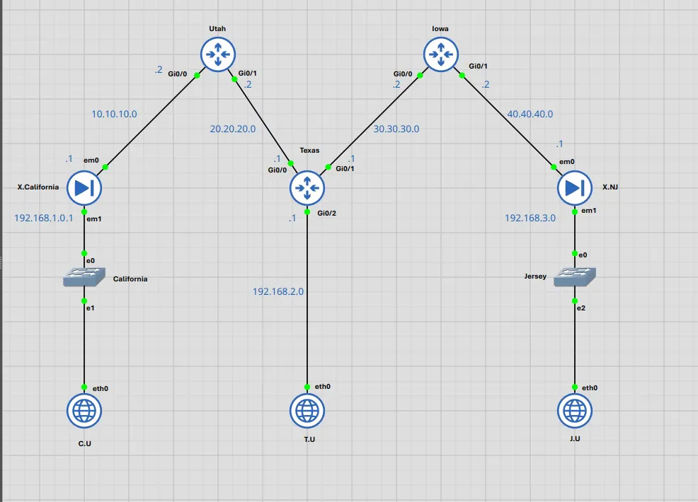
Step 1: Configuring the Transit Routers
We cannot analyse security boundaries without first building a functional routing substrate. To simulate a real-world provider network, I configured the Cisco routers with /30 point-to-point transit links. This limits broadcast domains and mimics standard WAN connectivity.
I applied the following static routing architecture to guarantee full reachability across the simulated Internet core:
Utah Router (West Transit Node)
| Destination Network | Subnet Mask | Next Hop (Gateway) | Purpose |
|---|---|---|---|
| 30.30.30.0 | 255.255.255.252 | 20.20.20.1 | Reach Texas to Iowa transit link |
| 40.40.40.0 | 255.255.255.252 | 20.20.20.1 | Reach New Jersey firewall WAN |
| 192.168.1.0 | 255.255.255.0 | 10.10.10.1 | Return traffic to California LAN |
| 192.168.2.0 | 255.255.255.0 | 20.20.20.1 | Reach Public Node LAN |
| 192.168.3.0 | 255.255.255.0 | 20.20.20.1 | Forward traffic toward Jersey LAN |
Texas Router (Central Transit Node)
| Destination Network | Subnet Mask | Next Hop (Gateway) | Purpose |
|---|---|---|---|
| 10.10.10.0 | 255.255.255.252 | 20.20.20.2 | Forward traffic toward California LAN |
| 40.40.40.0 | 255.255.255.252 | 30.30.30.2 | Forward traffic toward Jersey LAN |
| 192.168.1.0 | 255.255.255.0 | 20.20.20.2 | Forward traffic toward California LAN |
| 192.168.3.0 | 255.255.255.0 | 30.30.30.2 | Forward traffic toward Jersey LAN |
Iowa Router (East Transit Node)
| Destination Network | Subnet Mask | Next Hop (Gateway) | Purpose |
|---|---|---|---|
| 10.10.10.0 | 255.255.255.252 | 30.30.30.1 | Forward traffic toward California LAN |
| 20.20.20.0 | 255.255.255.252 | 30.30.30.1 | Reach Utah to Texas transit link |
| 192.168.1.0 | 255.255.255.0 | 30.30.30.1 | Forward traffic toward California LAN |
| 192.168.2.0 | 255.255.255.0 | 30.30.30.1 | Reach Public Node LAN |
| 192.168.3.0 | 255.255.255.0 | 40.40.40.1 | Return traffic to Jersey LAN |
To establish these links, I used standard Cisco IOS commands. For example, the Utah router required specific interface assignments to bridge the California firewall and the Texas core. Similarly, the Texas router functions as the pivot point for the entire topology:
! Texas Router Interface Configuration
interface GigabitEthernet0/0
 description Transit Link to Utah Router
 ip address 20.20.20.1 255.255.255.252
 no shutdown

interface GigabitEthernet0/1
 description Transit Link to Iowa Router
 ip address 30.30.30.1 255.255.255.252
 no shutdown

! Iowa Router Interface Configuration
interface GigabitEthernet0/0
 description Transit Link to Texas Router
 ip address 30.30.30.2 255.255.255.252
 no shutdown

interface GigabitEthernet0/1
 description Link to New Jersey pfSense WAN
 ip address 40.40.40.2 255.255.255.252
 no shutdown
Step 2: Basic pfSense Interface Configuration
With the routing substrate confirmed, we can now turn our attention to the firewalls. If you need a refresher on getting the firewall software running from scratch, please check out my previous guide on pfSense installation and initial setup.
For this lab, I kept the base configuration minimal. I accessed the console menu on both the California and New Jersey firewalls to assign their respective WAN and LAN IP addresses. Once the interfaces were up and I could successfully ping across the simulated internet, I logged into the web GUI to begin the IPsec build.
Step 3: Configuring the IPsec VPN
Building the VPN requires two distinct phases. Understanding both phases is critical because network engineers often focus only on the encrypted data flow, ignoring how the tunnel actually builds itself.
Phase 1: IKEv2 (The Handshake)
Phase 1 uses the Internet Key Exchange version 2 (IKEv2) to establish the initial security association. Think of your firewalls as strict bouncers. Before they open a private door for guests, the bouncers at both locations must call each other, verify their identities using a secret password, and agree on a secure language to speak.
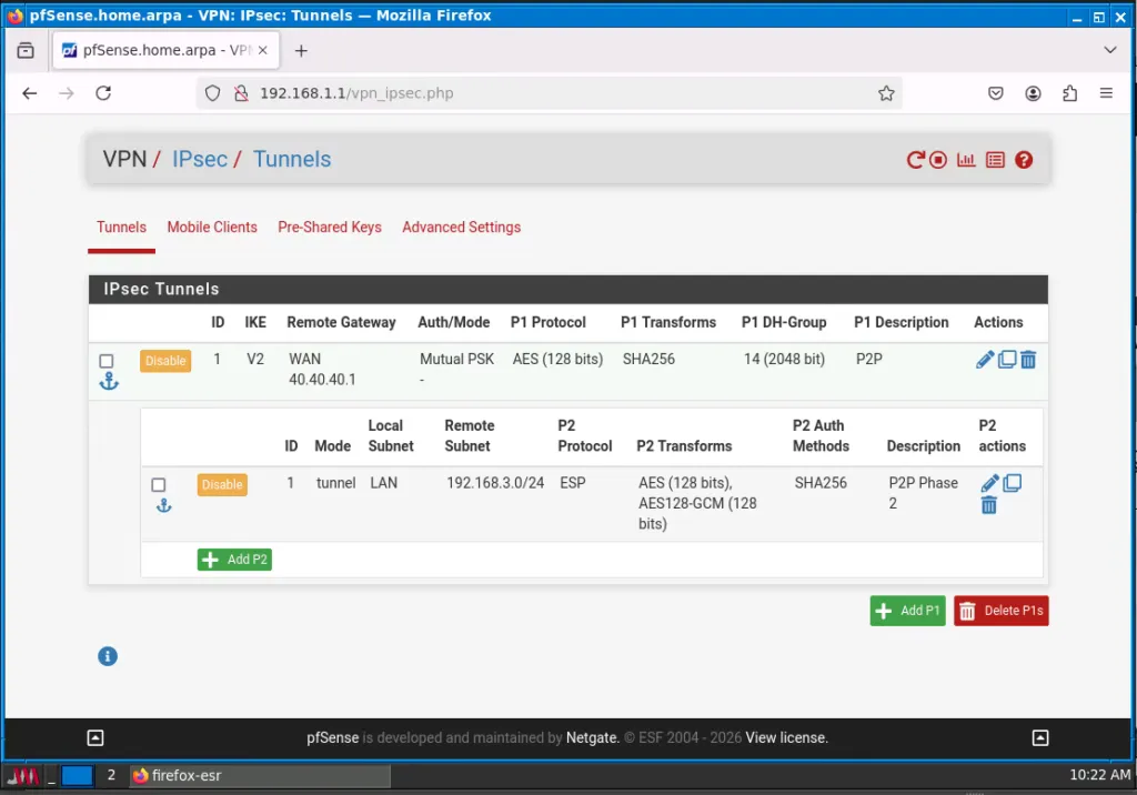 X.Califionia Firewall
 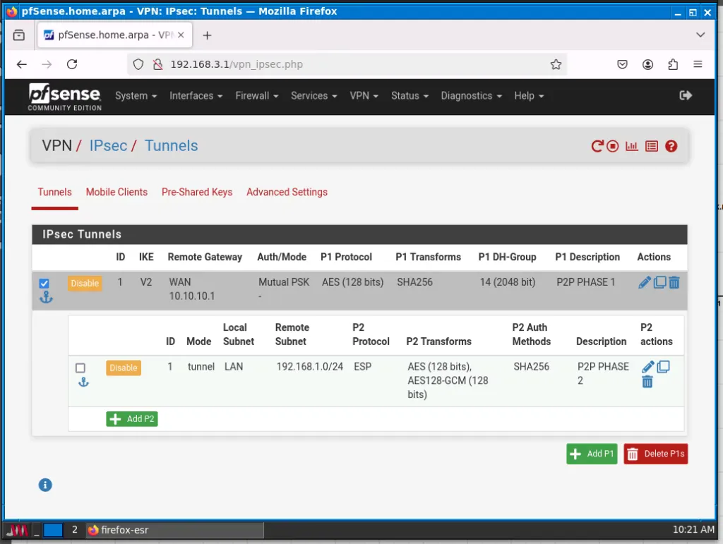 X.NJ Firewall IPSec Tunnel Configuration as seen on X.California and X.NJ Firewalls
I navigated to VPN > IPsec > Tunnels and created a Phase 1 entry with these parameters:
- Key Exchange Version: IKEv2.
- Remote Gateway: 40.40.40.1 (New Jersey WAN).
- Authentication Method: Mutual PSK (Note: While we use a Pre-Shared Key here, Mutual Certificate authentication is the standard recommendation for production environments).
- Encryption/Hash/DH: AES-CBC (128-bit), SHA256, Group 14.
Phase 2: ESP (The Payload)
Once the bouncers establish trust, they build the actual secure tunnel. This is Phase 2, which uses the Encapsulating Security Payload (ESP). In this phase, we define exactly which local subnet may talk to which remote subnet.
- Mode: Tunnel IPv4.
- Local/Remote Network: LAN subnets (192.168.1.0/24 and 192.168.3.0/24).
- Encryption Algorithms: AES (128-bit) and AES-128-GCM.
Step 4: Wireshark Analysis
To observe the negotiation in real-time, I restarted the firewalls and immediately began a Wireshark capture at the transit points.
When the session initiates, we see four critical UDP 500/4500 packets:
- IKE_SA_INIT (Messages 1 and 2): The firewalls exchange cryptographic capabilities and nonces. They have not authenticated yet, but they have established a shared secret to encrypt all subsequent messages.
- IKE_AUTH (Messages 3 and 4): This stage authenticates the firewalls. Under the protection of the temporary IKE SA, they exchange identities (IDi/IDr) and verify the PSK. This stage also negotiates the CHILD_SA (the actual encrypted tunnel for your data).
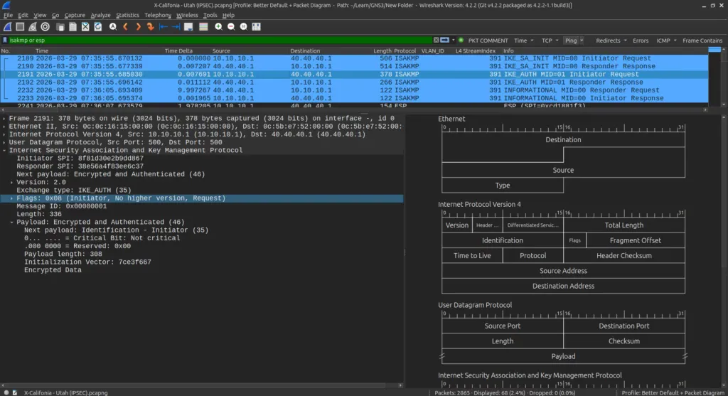 IKE_AUTH
 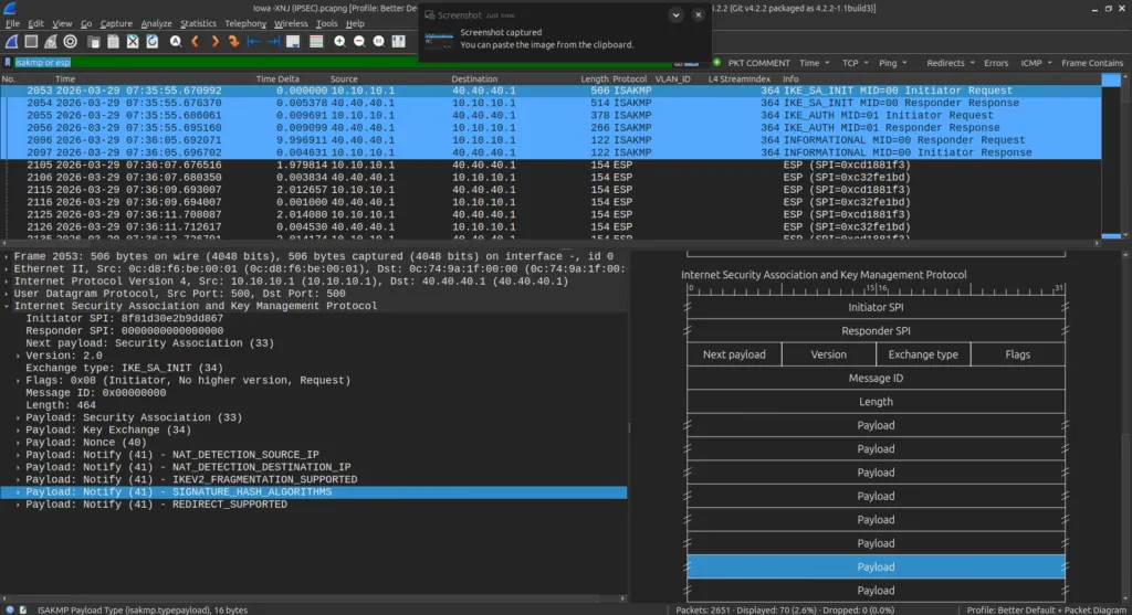 IKE_SA_INIT Wireshark Capture of the IPSEC session initiation between the two Firewalls.
Step 5: Validating Traffic with Logic
To confirm the tunnel’s security, I ran two different ping scripts simultaneously. This creates a side-by-side comparison of secure and insecure communication across the same physical wires.
Encrypted Traffic (California LAN to New Jersey LAN):
while true; do ping -c 1 192.168.3.10 > /dev/null; sleep 2; doneCleartext Traffic (California LAN to Public Transit Node):
while true; do ping -c 1 192.168.2.10 > /dev/null; sleep 2; doneResults on the Wire: The Packet’s Journey
To understand why this lab holds water, we must trace exactly what happens to the packet as it leaves the endpoint. It is not just about “encryption”; it is about encapsulation.
1. Inside the LAN: The California PC generates a standard ICMP request. At this stage, the packet is naked. The source IP is 192.168.1.10 , and the destination is 192.168.3.10. If a sniffer sat on the internal switch, they would see everything.
2. Crossing the Security Edge (The Firewall): As the packet hits the California pfSense firewall, the IPsec policy intercepts it. Because the destination matches our Phase 2 “interesting traffic” definition, the firewall does not simply route it. Instead, it wraps the entire original packet inside a new envelope. This is the ESP header (Protocol 50).
3. The Transit Core (The ESP Tunnel): Once the packet enters the tunnel, its identity changes completely. ESP encapsulated the traffic fully between Site A and Site B. The pfSense WAN IPs (10.10.10.1 and 40.40.40.1) masked the private endpoint addresses perfectly. To the Utah and Texas routers, this is no longer a “ping” but is just an encrypted data stream in a Site-to-Site IPSec VPN.
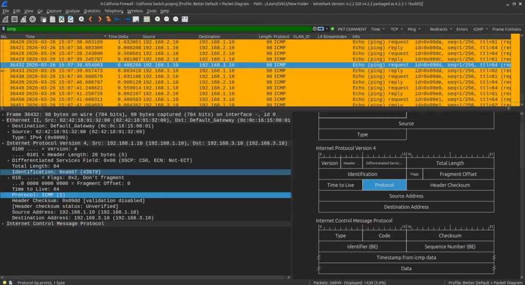
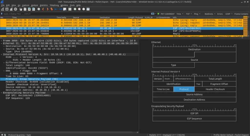
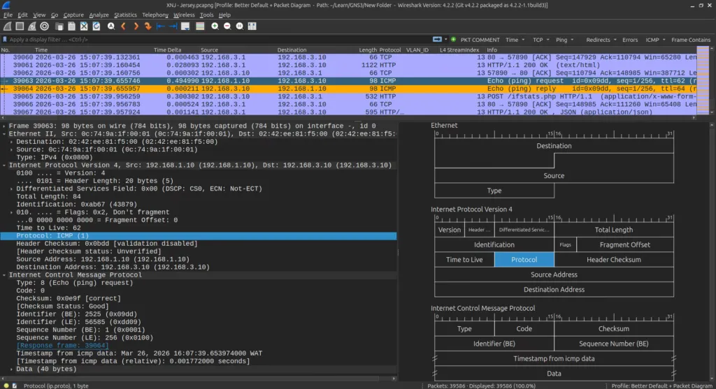 The Images Show the flow of ICMP traffic as it flows from the C.U. Endpoint through the firewalls, encrypted to the J.U Endpoint
4. The Comparison Baseline: In contrast, the public-facing traffic exposed every detail to anyone sniffing the wire. By following the ICMP packets from California (C.U) to the Public Node (T.U), we can see the naked IP headers in every capture at Utah and Texas. Unlike the VPN traffic, these packets retain their 192.168.1.10 source address throughout the entire transit core. This confirms that without the IPsec tunnel, your internal network addresses are visible to every hop along the internet backbone.
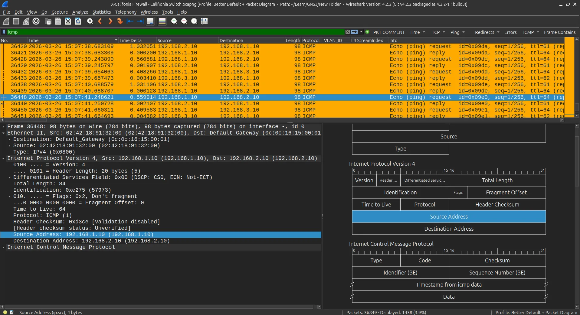
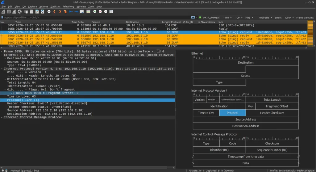
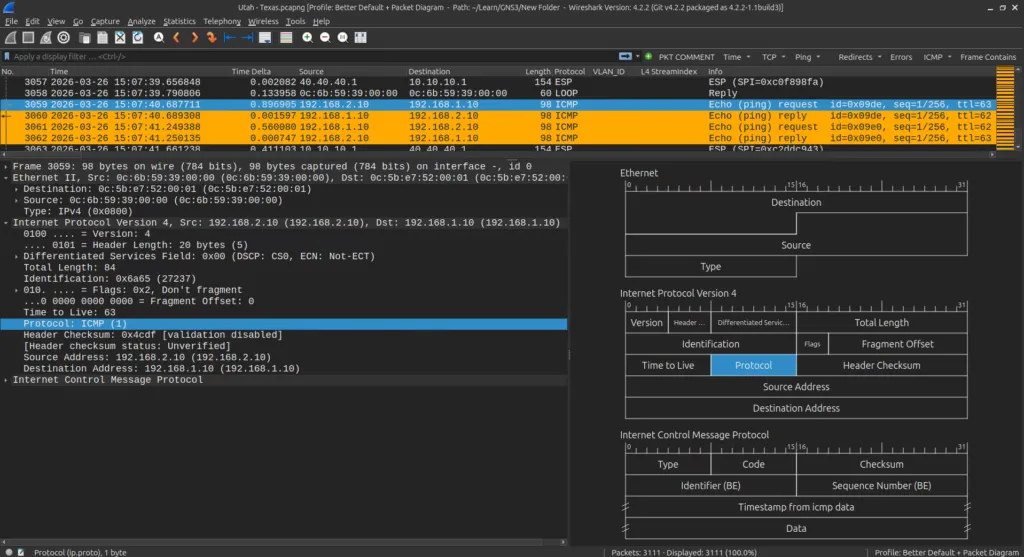 The Images Show the flow of ICMP traffic as it flows from the C.U. Endpoint through the firewalls unencrypted to the T.U endpoint
Conclusion: Why This Matters for Small Business
Configuring a site-to-site IPsec VPN provides more than just technical satisfaction. For a small business in Nigeria or elsewhere, this configuration directly replaces expensive leased lines or third-party MPLS services. This simple change potentially saves thousands in operational costs. If you skip this, you are essentially leaving your internal company data exposed on a public highway.
In conclusion, a site-to-site IPsec VPN allows you to extend internal services like file shares or accounting software between remote branches with cryptographic certainty. It is a cost-effective, easy-to-deploy WAN alternative that ensures your private data stays private, even when it is forced to travel across the public highway of the internet.
Further Reading: