

Having installed the pfSense firewall, it’s crucial to establish firewall rules that safeguard your network’s perimeter. Understanding how these rules are configured on pfSense is essential for robust network security. In this post, I will share a sample setup I designed using GNS3 for demonstration purposes.
THE SETUP
Our network architecture includes a pfSense firewall with three interfaces: a WAN and two LANs. One of these LAN interfaces is segmented into three VLANs—1, 10, and 20. VLAN 1 is dedicated to management, while VLANs 20 and 10 serve as user VLANs, presumably for different departmentals within an organization.
Additionally, the second LAN interface of the firewall accommodates a server within the DMZ, which hosts a suite of web applications. The intricacies of this setup are depicted in the image below.
WAN NETWORK = 50.50.50.0/30
Firewall Address = 50.50.50.1
Firewall Gateway = 50.50.50.2
VLAN 1 network = 10.10.1.0/24
VLAN 10 network = 10.10.10.0/24
VLAN 20 network = 10.10.20.0/24
DMZ network = 20.20.1.0/24
Webserver Address = 20.20.1.3
Internet User = 50.50.50.6
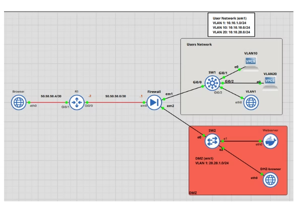
Other connections outside the firewall are set up to mimic incoming traffic from the WAN. Although these are not the primary focus of this article, they are included simply for illustrative purposes.
STATEFUL FIREWALL
Pfsense is a stateful firewall which tracks outbound connections originating from within the network. This feature ensures that responses to these initiated connections are automatically permitted, negating the need for separate inbound configurations. The firewall maintains a state table where it logs initiated states, allowing it to recognize and permit returning connections. The nature of the firewall significantly influences the configuration strategy.
FIREWALL RULES.
We can access Pfsense by navigating to firewalls > Rules. From there, as seen in the image below, you will see all the interfaces we discussed earlier from the WAN, All the VLANs and the DMZ. Please note that I renamed the interface accordingly for easy identification. Changing the interface name isn’t that hard, navigate to interfaces from the menu bar, select the interface you want to rename and set the name.
FLOATING RULES
Rules placed in this section override those of other interfaces. Any rule added here affects all interfaces, therefore, it must be used with caution. While we will not be implementing Floating Rules in our current configuration, it is important to remember the relivance of this section as it would be used in future.
WAN RULES:
This section deals with configuring rules for the WAN interface. Before adding rules to this interface, the first step is to go to the interface page where you renamed the interfaces.
When you navigate to the rules page for the WAN interface, you will notice that PFsense automatically generates two rules: one that blocks bogon networks and another that blocks private networks. In a production environment, I would typically leave these enabled as they provide an extra layer of security against IP addresses that could be used for malicious activities.
However, for this simulation, I would disable them to prevent interference, as we might be using IP addresses that match the above conditions. Therefore, click on the gear icon next to the rules, which will take you to the interface settings page where you can easily uncheck the boxes that add these rules automatically. As we proceed with our configuration, I will continue to disable these for the other interfaces, solely for the purpose of this simulation.
By default, PFsense blocks all incoming connections on the WAN interface. For most basic configurations, this setting is usually sufficient. However, I recommend creating the rule to log blocked connections for record-keeping purposes. Additionally, the rule provides reassurance that unwanted incoming connections are blocked by default.
- Click on the Add button
- Change the Action to “Block”
- Address Family “IPv4” (I would stick to IPv4 for in this simulation)
- Change Protocol to “Any”
- Source “Any”
- Desitnation “Any”
- Log packet that are handled by this rule “Check”
- Description “Explicit Block Rule”
- Make sure you save.
You can leave most of the other settings as it was for now, Save and dont forget to hit “Apply Changes” lets leave the WAN for now and move on other interfaces.
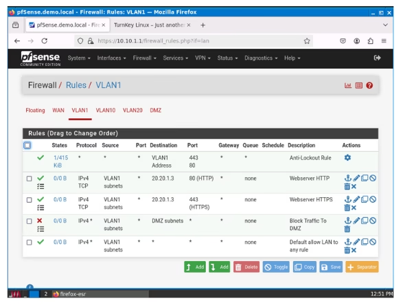
VLAN 1
Upon accessing this interface, four default rules are automatically generated. The first rule ensures that the admin user is not locked out of pfSense. Following that, there’s a rule similar to the one we established in WAN that blocks bogon networks. The final two rules permit IPv4 and IPv6 traffic from VLAN 1 by default.
These rules are auto-generated for this interface as it’s configured for web configuration access to pfSense. As a result, pfSense generates rules that are considered suitable. As previously stated, I would eliminate the bogon network rule and the IPv6 rule, while keeping everything else unchanged.
Additionally, I would edit the IPv4 rule and enable the checkbox that allows me to log firewall states applicable to the rule. This is a standard practice in a production environment for troubleshooting purposes. In such an environment, this interface (VLAN1) would serve as the management VLAN, which the administrator could use for tasks such as logging into the firewall and managing other network devices that may also be located in this VLAN. Consequently, I would prevent other interfaces from initiating communication with this VLAN, while allowing this VLAN to communicate with them. Despite being a management VLAN, the DMZ should be off-limits to any interface, including this one; any management of the resources in the DMZ should be conducted within the DMZ itself.
Let’s implement a rule that blocks this interface from communicating with the DMZ. Stateful firewalls automatically allow return traffic to the source where it was initiated; therefore, there’s no need to add an associated rule for incoming traffic. This principle influences how we create rules in pfSense, as we typically configure an interface to prevent a rule from being initiated, rather than blocking an incoming connection. Provided that the rule initiated from a source is permitted to exit and has been entered into the state table, an associated incoming rule would be allowed by default. We will encounter similar configurations as we proceed with this lesson.
- Action “Block”
- Address Family “IPv4”
- Protocol “Any”
- Source “VLAN 1 subnet”
- Destination “DMZ Subnet”
- Log Packets that are handled by this rule “check”
- Description “Block Traffic to DMZ” (You can describe it however you please)
- Save.
- Drag the created Rule above the default allow rules
- Apply changes
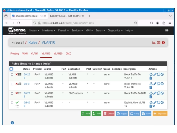
VLAN 10
Unlike what we saw when configuring VLAN 1 rules, VLAN 10 interface’s rules page shows only a default rule aimed at blocking bogon networks and nothing else. Besides removing this default rule as discussed, this means we need create and implement our own set of rules tailored to the requirements of this interface.
The initial rule we will establish is one that allows internet access to users within this network.
- Action “Pass”
- Address Family “IPv4”
- Protocol “Any”
- Source “VLAN 10 Subnet”
- Destination “Any”
- Check Log Data packets (optional but recommended)
- Save and Apply
To ensures that in the event of a network breach, the impact is contained, thereby limiting lateral movement within the network.
Hence, the next rule is the to create rule that blocks inblound VLAN 10 from communication with VLAN 1, 20 and DMZ
- Action “Block”
- Address Family “IPv4”
- Protocol “Any”
- Source “VLAN 10 Subnet”
- Destination “VLAN 1 subnet”
- Description “Block traffic to VLAN 1”
- Check Log Data packets
- Save and Apply
Go ahead of configure similar rules for VAN 20 and DMZ.
Ensure you reorder your rules correctly, which can be accomplished by dragging and dropping. Don’t forget to save and apply the changes after reordering.
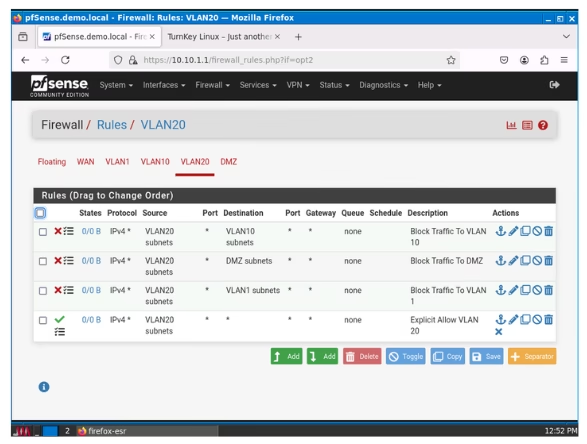
VLAN 2O
To get straight to the point, we simply need to replicate the configuration we used for VLAN 10, altering the parameters to block for VLAN 1, 10 and DMZ.
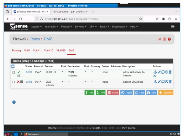
DMZ
In the DMZ, we have already prevented users from the other VLANs from initating a connection to the DMZ, subsequently we need to create similar rules that prevent the DMZ from communicating with other VLANS.
This single rule below would prevent the DMZ from communicating with anyone by default. Please note that Pfsence typcally block any rules by default however i prefer to create these rules manually to allow me track what via logs.
- Action “Block”
- Address Family “IPv4”
- Protocol “Any”
- Source “DMZ Subnet”
- Destination “Any”
- Description “Eplicit DMZ block”
- Check Log Data packets
- Save and Apply
I would create one more rule which allows only the webserver communicate with the WAN address incase the webserver need to connect to the internet for any aprcific API or resource as determined by the developer, typically you would only allow that specific protocol but this is a lab enviroment hence we can make assumptions.
- Action “Pass”
- Address Family “IPv4”
- Protocol “Any”
- Source “20.20.1.3” That is the IP address assigned to the Webserver
- Destination “WAN Subnet”
- Description “Allow Webserver to WAN”
- Check Log Data packets
- Save and Apply
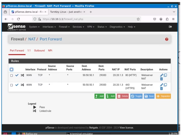
HOW TO ALLOW USERS FROM THE INTERNET TO ACCESS OUR WEBSERVER FROM THE INTERNET
If you’re operating a public-facing service like a web server in our simulated lab, having internet access to this server is crucial. We can implement port forwarding in pfSense along with some firewall rules to achieve this. The web server has been set up to be accessible using the IP address 20.20.1.3 on ports 80 (HTTP) and 443 (HTTPS)—but that’s a tutorial for another day.
In front of our firewall, we have a router and a browser which will act as a user on the internet attempting to access the web server. Let’s go to Firewall > NAT on pfSense to add a new NAT Rule.
- Click Add
- Interface “WAN”
- Address Family “IPv4”
- Protocol “TCP”
- Destination “Address or Alias – 50.50.50.1 (our WAN address)
- Destination port “Other – 29300” (Uses only non assigned TCP ports)
- Redirect target IP “Address Or Alias – 20.20.1.3”
- Redirect target port “HTTP” (Or enter custom port 80)
- Description “Enter NAT rule description”
- NAT reflection “System default”
- Filter Rule associatio “Create New associated NAT rule” (An associated rule related to this rule would be created in WAN rules page.
- Save.
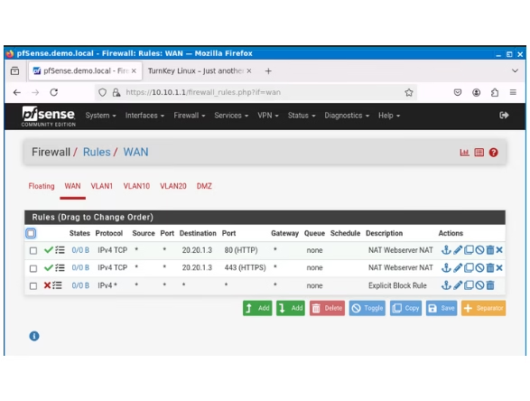
For HTTPS, repeat the same process. Then, go back to the Firewall WAN Rules and adjust the rules you’ve just set up. Choose the new rules, turn on Logging, and move them above the Explicit Block Rule we made earlier. Don’t forget to save and apply the changes.
Regarding local users, since I have blocked them from accessing resources in the DMZ, I would create a rule on the relevant VLAN to allow them access only to the webserver.
- Action “Pass”
- Address Family “IPv4”
- Protocol “Any”
- Source “VLAN 1”
- Destination “Address or Aliase – 20.20.1.3”
- Destination port “HTTP-80”
- Description “Allow Webserver HTTP
- Check Log Data packets
- Save and Apply
TESTING
I ran some test to see if our configured rules worked. First we would test if We can ping various interfaces from to others including tryuing to reaching our gatway router.
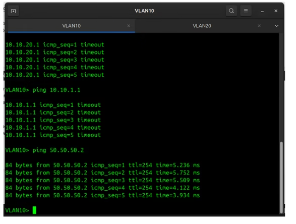
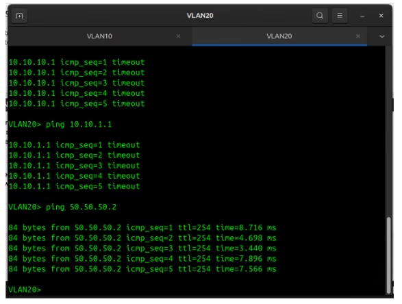
From the image above, the PC in VLAN 10 couldn’t reach VLAN 20 or VLAN 1, but it was able to reach the gateway, indicating it should be able to access the internet. A similar occurrence is seen in the image below with VLAN 20. Although I didn’t show the pings to the DMZ, it was also unreachable; I simply forgot to capture it when taking screenshots of the tests.
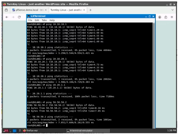
In the subsequent test, I conducted a ping from VLAN 1 to all interfaces, including the DMZ, which I remembered this time. As the management VLAN, it successfully reached both VLAN 10 and 20, but, as intended, it could not reach the DMZ. Additionally, it was able to reach the gateway.
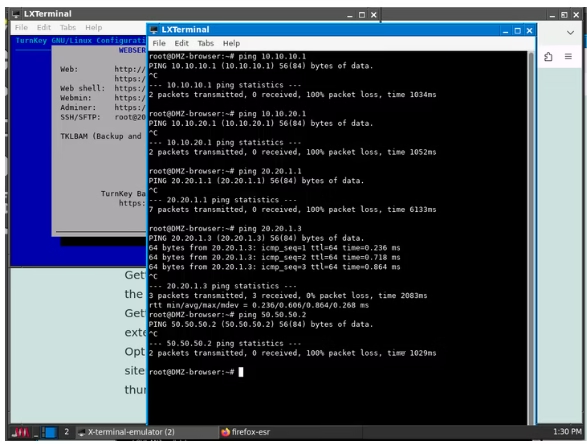
The image above displays the results for a ping in the DMZ, which was unsuccessful in reaching any destination except for the web server within its own subnet.
With the ICMP test completed, let’s proceed to test if we can connect to our web server from outside the network based on our NAT rules. The image below indicates that we were successful in reaching the web server using the WAN address and port number 29300, which were specified in our NAT configuration.
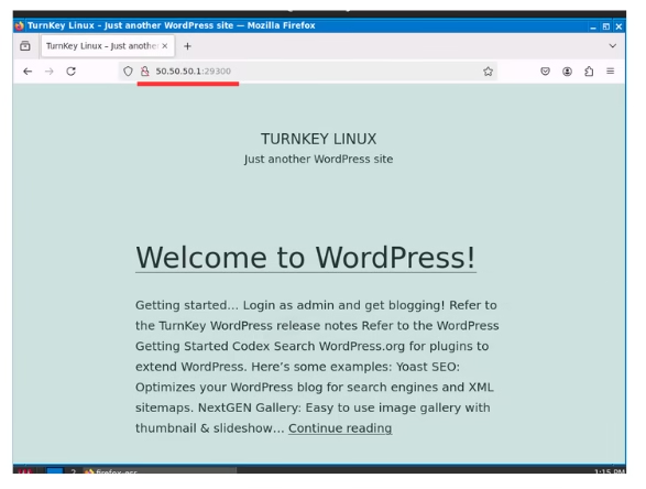
The last step before completion is to verify that users within the local network can access the Webserver without an internet connection. To achieve this, we set up an allow rule in VLAN 1 that permits HTTP(s) traffic to the Webserver exclusively. The image below demonstrates that we successfully accessed the webserver from VLAN 1, even though pinging the DMZ from VLAN 1 was not possible.

I believe this guide has provided a solid baseline for anyone who wants to understand how to configure firewall rules in pfSense. I apologize for the quality of some of these screenshots; I didn’t give much thought to the output quality. However, I suggest you try to replicate this in your home lab as much as possible and don’t forget to leave a comment if you have questions about the topic or any other subject.
Leave a Reply