
Building upon the foundational concepts of Network design covered in the previous lesson, where we delved into the intricacies of subnetting IPv4 addresses to be used in this lesson series, we now shift our focus specifically to routers. In this lesson, we will explore the various router types available in Packet Tracer and guide you through their setup for our ongoing project
When setting up a Packet Tracer simulation, the first challenge is selecting the right devices, like switches, routers, and firewalls, for the project. This lesson concentrates on routers, delving into the diverse router types offered in Packet Tracer. We’ll identify the router that best suits our needs and guide you through the setup process for this particular project.

Considerations For Choosing Routers In Packet Tracer
- Network Size and Complexity: The size and complexity of your network topology will significantly impact the type of router you require. For small and straightforward networks with basic routing tasks, routers like the Cisco 819, 1841, or 2620XM are generally sufficient. However, for larger and more intricate networks that demand advanced routing protocols, high-bandwidth capabilities, and sophisticated configurations, routers like the Cisco 2811, 2901, or 4321 are better suited.
- Features and Functionality: Assess the specific features and functionalities you need to support your network’s requirements. Consider the types of interfaces required (Ethernet, serial, etc.), the routing protocols supported (RIP, OSPF, BGP, IPv6), and any additional features like security, QoS, or voice support.
- Performance and Scalability: Choose a router that can handle the anticipated traffic load and routing calculations. Consider the processing power (CPU and memory) and the availability of expansion slots (AIM slots or WIC slots) for future growth and flexibility.
- Learning Objectives: If you are a beginner exploring Cisco networking fundamentals, simpler routers like those mentioned for small networks are ideal for learning the basics. For advanced users seeking to delve into complex configurations and advanced protocols, more sophisticated routers with wider functionalities are suitable.
- Compatibility and Availability: Ensure the router you choose is compatible with the version of Cisco Packet Tracer you are using. Additionally, check for readily available documentation, tutorials, and online communities for support and troubleshooting.
By carefully evaluating these factors, you can effectively select the most appropriate router for your specific Cisco Packet Tracer needs, ensuring a smooth and productive learning experience
Cisco Routers Available In Packet Tracer
There are a couple of routers available on packet tracer but these are the ones i consider even if i were to pick, this isnt an exhustive list but its some of the routers avaialible on
| SN | MODEL | DESCRIPTION | INTEGRATED PORTS | EXPANDABLE SLOTS |
| 1 | Cisco 2621XM ISR Router | Compact and cost-effective router suitable for branch offices and remote deployments, featuring enhanced performance and support for additional interfaces. It is well-suited for situations requiring higher bandwidth and more complex network configurations. | FastEthernet (x2) | WIC (x2) AIM (x1) |
| 2 | Cisco 1941 ISR | A legacy router model still widely used in educational settings and for training purposes. It provides a basic platform for learning fundamental routing concepts and configuring Cisco routers | GigabitEthernet (x2) | HWIC (x2) |
| 3 | Cisco 2901 ISR | A successor to the 1941 ISR, offering improved performance and support for additional features. It is a popular choice for teaching and learning routing principles and configurations. | GigabitEthernet (x2) | HWIC (x4) |
| 4 | Cisco 2911 ISR | A high-performance router designed for demanding network environments. It offers multiple Ethernet and WAN interfaces, support for advanced protocols, and the ability to handle high traffic volumes | GigabitEthernet (x3) | HWIC (x4) |
| 5 | Cisco 829 ISR | A more compact and cost-effective router suitable for small to medium-sized businesses and branch offices. It provides adequate performance for basic networking needs and offers a range of Ethernet and WAN interface and additional interfaces. | GigabitEthernet (x2) GigabitEthernet SwitchPorts (x4) Cellular (x | No Expandable ports |
| 6 | Cisco 4321 ISR | A high-performance router designed for large enterprises and demanding network environments. It offers multiple Ethernet and WAN interfaces, support for advanced protocols, and the ability to handle high traffic volumes. | GigabitEthernet (x2) | NIM (x2) |
What Are Routers?
Before delving into router selection, let’s take a step back and revisit the fundamentals of routers and their role in networking. While I anticipate that everyone following this blog series has some basic networking knowledge, including familiarity with routers and switches, a quick refresher never hurts.
Imagine your computer network as a bustling city of Lagos, with data packets representing the vehicles traversing its streets. Routers act as the intelligent traffic controllers, directing data packets along their optimal routes to their intended destinations. They operate at the network layer of the OSI model, analyzing the destination addresses of data packets and making informed decisions about their paths.
Routers connect various networks, enabling seamless communication between devices across different network segments. They can connect LANs (Local Area Networks), WANs (Wide Area Networks), and even the Internet. Common connection types supported by routers include Ethernet, Fast Ethernet, Gigabit Ethernet, and fiber optic connections.
In essence, routers handle inter-network communication, while switches handle intra-network communication. Routers are responsible for the broader, global network connectivity, while switches manage the local traffic within a specific network segment
The Selection
I selected the Cisco 2901 ISR for this tutorial due to its well-established reputation for teaching and learning routing concepts and configurations. Additionally, its support for four HWIC cards enables the expansion of connectivity beyond the two integrated Gigabit Ethernet interfaces, which isn’t enough for our specific use case.
For my implementation, I utilized two compatible modules:
- HWIC-1GE-SFP: A single-wide HWIC with one Small Form-Factor Pluggable (SFP) slot.
- GLC-LH-SMD: A Gigabit Single Mode fiber SFP Module.
Combined, these modules provided four additional Gigabit Fiber WAN ports for interconnecting my routers, effectively supplementing the integrated Ethernet ports. Fiber cable is used to connect the WAN links between the routers and Ethernet cable is used for connecting the the switches to the routers.
The Interface Setup
- Open Packet Tracer on your device
- Drag your first router into the workspace as seen in the image blow
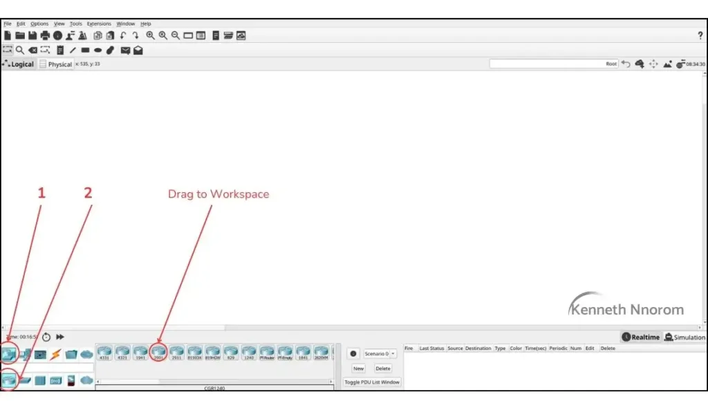
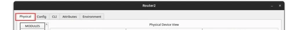
- Click on the Router to open up the set up page
- Select “Physical” on menu bar of the router setup
- From here, From number ‘1’ in the image below, we need to turn on off the router to add modules
- Drag module ‘3‘ into slot ‘a‘.
- Drag module labelled ‘2‘ into slot’b‘

- Repeat the process for the remaining 3 HWIC slots.
- Power the router back ON
After completing the process, navigate to the “Config” tab. Under the “Interfaces” section, you will notice four new interfaces named GigabitEthernet0/0/0 to GigabitEthernet0/3/0. These four new interfaces will be used to connect your routers.

To streamline the process, you can duplicate the router configuration while ensuring that the display names are appropriately modified for easy identification. In my instance, I have seven routers named LAGOS, ABUJA, DELTA, KANO, BORNU, LAG-GEN, and GEN LINK. You can choose any names you prefer, but keep track of them as we will use them to identify the routers throughout the process.
Connect the Route Links
I recommend manually connecting each link to maintain control over the specific ports used for your connections. This will prove beneficial during configuration.
Follow the steps outlined in the image below:
- Select “Connectors” from the menu.
- Choose “Fiber Cable.

Utilize the table below to complete the router connections:
| SN | ROUTER A | ROUTER A INTERFACE NAME | ROUTER B INTERFACE NAME | ROUTER B |
| 1 | LAGOS | g0/0/0 | g0/0/0 | LAG-GEN |
| 2 | LAGOS | g0/1/0 | g0/0/0 | ABUJA |
| 3 | ABUJA | g0/1/0 | g0/1/0 | GEN-LINK |
| 4 | ABUJA | g0/2/0 | g0/2/0 | DELTA |
| 5 | LAG-GEN | g0/1/0 | g0/0/0 | GEN-LINK |
| 6 | GEN-LINk | g0/2/0 | g0/0/0 | DELTA |
| 7 | GEN-LINK | g0/3/0 | g0/0/0 | BORNU |
| 8 | DELTA | g0/1/0 | g0/1/0 | KANO |
| 9 | KANO | g0/0/0 | g0/1/0 | BORNU |
Subnet Distribution For The Routes
In my previous post on IPv4 Subnetting, I mentioned that I utilized a /30 subnet mask (255.255.255.252) when implementing the 20.20.20.0/24 network, resulting in four host addresses with only two usable ones. The following table illustrates how I plan to distribute the subnetworks among the router links
| SN | ROUTE | NETWORK | HOST A IP | HOST B IP | BROADCAST |
| 1 | LAGOS — LAG-GEN | 20.20.20.0 | 20.20.20.1 – Lagos | 20.20.20.2 – Lag-Gen | 20.20.20.3 |
| 2 | LAGOS — ABUJA | 20.20.20.4 | 20.20.20.5 – Lagos | 20.20.20.6 – Abuja | 20.20.20.7 |
| 3 | ABUJA — GEN-LINK | 20.20.20.8 | 20.20.20.9 – Abuja | 20.20.20.10 – Gen-Link | 20.20.20.11 |
| 4 | ABUJA — DELTA | 20.20.20.12 | 20.20.20.13 – Abuja | 20.20.20.14 – Delta | 20.20.20.15 |
| 5 | LAG-GEN — GEN-LINK | 20.20.20.16 | 20.20.20.17 – Lag-Gen | 20.20.20.18 – Gen-Link | 20.20.20.19 |
| 6 | GEN-LINK — DELTA | 20.20.20.20 | 20.20.20.21 – Gen-Link | 20.20.20.22 – Delta | 20.20.20.23 |
| 7 | GEN-LINK — BORNU | 20.20.20.24 | 20.20.20.25 – Gen-Link | 20.20.20.26 – Bornu | 20.20.20.27 |
| 8 | DELTA — KANO | 20.20.20.28 | 20.20.20.29 – Delta | 20.20.20.30 – Kano | 20.20.20.31 |
| 9 | BORNU — KANO | 20.20.20.32 | 20.20.20.33 – Bornu | 20.20.20.34 – Kano | 20.20.20.35 |
To ensure we keep this article concise, we’ll delve into the practical aspects of connecting and configuring our network devices in the next installment.
In the follow-up article, we’ll guide you through the process of connecting the switches and PCs to their respective routers using Packet Tracer..
Following the connections, we’ll assign IP addresses to the router interfaces as outlined in the table above. Also, remember the 10.10.10.0/28 networks from the initial article? These networks will be assigned to the switches and PCs connected to the respective routers, creating distinct user networks.
Stay tuned for the next article as we embark on this practical journey to bring our network to life
Leave a Reply