
We’re ready to start linking the switches to our networks, even though we have yet to configure the routes on the routers. I intend to configure all forms of connection part of the lesson before configurations. With that, we can proceed to our task for this lesson.
CONNECTION TABLE
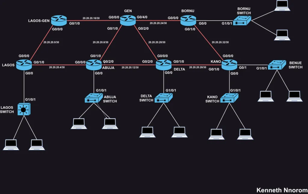
Similar to our previous process of connecting the routers, we’ll utilize the connection tool to link the interfaces on the switch to the corresponding interface on the routers. It’s important to recall that we exclusively used the Fiber interfaces for router connections, leaving us with two available Ethernet (RJ45) interfaces for connecting the switches to the routers.
| SN | Switch ID – Interface Vlan1 | Router ID – Interface | Network | Usable IPs |
| 1 | Lagos Switch 1 – g1/0/1 | Lagos – g0/0 | 10.10.10.0/28 | 10.10.10.1 – 14 |
| 2 | Abuja Switch – g1/0/1 | Abuja – g0/0 | 10.10.10.16/28 | 10.10.10.17 – 30 |
| 3 | Delta Switch – g1/0/1 | Delta -g0/0 | 10.10.10.32/28 | 10.10.10.33 – 46 |
| 4 | Kano Switch – g1/0/1 | Kano – g0/0 | 10.10.10.48/28 | 10.10.10.49 -62 |
| 5 | Benue Switch – g1/0/1 | Kano – g0/1 | 10.10.10.64/28 | 10.10.10.65 – 78 |
| 6 | Bornu Switch – g1/0/1 | Bornu – g0/1 | 10.10.10.80/28 | 10.10.10.81 – 94 |
How Switch Configuration Differs From Router Configurations
Routers act as hubs, routing traffic between different networks. They require an IP address on each interface participating in routing. This allows them to communicate with devices on each connected network segment.
Unlike routers, switches focus on forwarding traffic within a single network segment. They don’t typically need IP addresses on individual interfaces for data traffic.
However, switches require an IP address for management purposes. This is often assigned to the VLAN 1 interface, allowing remote access and configuration via Telnet, SSH, or web interfaces. This management network is usually separate from user traffic for security reasons.
We would revisit the con concept of Vlans in detail but for now, we just need to assign the Vlan1 to the switch for management and troubleshooting purposes
BASIC SWITCH CONFIG
Similar to what we did with the router, navigate to the CLI section of the switch and follow the following commands
switch> enable
switch# config t
switch(config)# hostname LS1(use preferred switch host mane as desired )
LS1(config)# interface vlan1
LS1(config-if)# ip address 10.10.10.1 255.255.255.240
LS1(config-if)# no shut
LS1(config-if)# exit
LS1(config)# exit
LS1# write memory
LS1#
You can apply these configuration steps to all the previously mentioned switches connected to the routers. Once we assign one of the available IP addresses to the switch, you can use the remaining 13 IP addresses to configure other network devices like printers and computers.
With that, we might be tempted to assume that physically connecting all routers, switches, and computers enables communication, but computer networks involve greater complexity. Physical connections represent only the initial stage; proper logical configuration is crucial for devices to communicate effectively and operate within the network.
This logical configuration enables administrators to manage access control, security, and resource allocation, ensuring a secure and efficient network environment.
Our current network configuration with routers by default limits the broadcast domain. This means computers in Lagos wouldn’t be able to communicate directly with computers in other states. For example, devices connected to the Lagos Switch cannot ping devices beyond the Lagos Router’s g0/0 interface, and vice versa. This limitation hinders the core functionality of a campus network, which is to enable communication across different locations.
In the next section, we’ll delve into routers, and routing protocols, and explore how to achieve the cross-location communication we desire.
Leave a Reply