
The Guide to Wi-Fi Network Design: Strategies for Success
A practical engineering guide to enterprise and hospitality Wi-Fi design: RF propagation, channel planning, SNR thresholds, airtime efficiency, and Fresnel zone clearance.
When designing a local area network, Wi-Fi is frequently where solid engineering plans run into messy physics. Unlike structured Ethernet cabling where packet transmission is bounded by twisted copper pairs and deterministic switching, RF environments are shared, unguided, and susceptible to severe physical attenuation.
In high-density environments like multi-tenant buildings, hotels, and enterprise offices across Lagos, poor Wi-Fi performance rarely stems from a lack of raw ISP bandwidth. More often, it is the direct result of bad RF planning: placing access points in hallways, bonding channels too wide in noisy bands, leaving transmit power on default maximums, and ignoring client device constraints.
Designing a resilient wireless network requires balancing RF propagation physics with client behavior. Here is how I approach wireless network design from the ground up.
1. Characterizing the Deployment Environment
Before touching configuration software or mounting hardware, an engineer must define the physical and operational constraints of the site.
- Physical Structure and Attenuation: Reinforced concrete walls, tinted glass, and elevator shafts attenuate RF signals drastically. A standard 2.4 GHz wave might drop 3 to 5 dB through dry drywall, but thick concrete walls can easily introduce a 12 to 20 dB loss, absorbing the signal almost entirely.
- Client Density and Concurrency: Calculating capacity is not just about total users; it is about concurrent active streams. Fifty mobile devices running background sync tasks demand a different airtime budget than fifty workstations running real-time video conferencing.
- Wired Uplink and Power Budget: Verify that edge switches support the required Power over Ethernet (PoE/PoE+) standards (802.3af/at) and that switch port bandwidth matches expected aggregate throughput.
2. Predictive Modeling and Floorplan Simulation
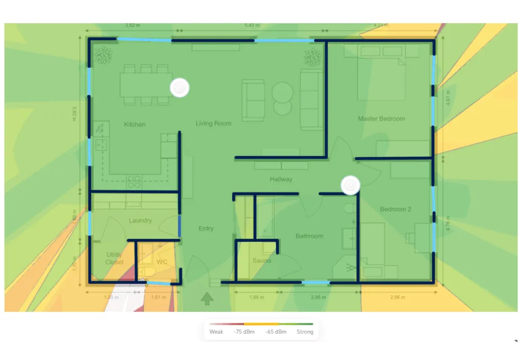 Sample predictive simulation in Ubiquiti Design Center (Floor plan source: RoomSketcher)
Predictive modeling software (such as Ubiquiti Design Center or Ekahau) allows you to simulate wall attenuation, predict coverage heatmaps, and identify dead zones before running a single drop of Cat6 cable.
However, simulations are only baseline estimates. Software models assume uniform materials, whereas real-world concrete often contains varying densities of rebar and moisture. Predictive layouts must always be validated with on-site active or passive survey measurements.
3. Designing for the Weakest Client Device
A common engineering mistake is designing around the high-gain antennas of enterprise access points rather than the constrained transmit power of mobile client devices.
Communication is bidirectional. An AP broadcasting at +20 dBm (100 mW) can easily reach a smartphone across two walls. But that smartphone, transmitting at only +10 to +14 dBm (10 to 25 mW) to conserve battery, cannot push its return signal back through the same concrete barriers. The result is a one-way connection where the client displays full Wi-Fi bars but experiences high packet loss and dropped frames.
To ensure stability, design cell boundaries around the transmit power and receiver sensitivity of your least-capable client. For standard voice and low-latency data, aim for a minimum received signal strength indicator (RSSI) of -60 dBm to -65 dBm at the cell edge.
4. Band Allocation: 2.4 GHz vs. 5 GHz
Every dual-band design must balance propagation distance against available spectrum:
- 2.4 GHz Band: Penetrates solid obstacles better and covers larger physical areas. However, it provides only three non-overlapping 20 MHz channels (1, 6, and 11) in most regulatory domains. With widespread interference from Bluetooth, microwaves, and neighboring networks, 2.4 GHz should primarily be reserved for legacy endpoints or low-throughput IoT telemetry.
- 5 GHz Band: Offers substantially wider spectrum with dozens of non-overlapping channels (including UNII-1, UNII-2/DFS, and UNII-3). While 5 GHz signals attenuate more rapidly through physical obstructions, the abundance of clean channels makes it the primary band for modern high-throughput enterprise traffic.
5. Managing Signal-to-Noise Ratio (SNR) and Interference
In wireless communication, raw signal strength is meaningless without sufficient contrast over background RF noise.
If an AP receives a client signal at -65 dBm against a typical noise floor of -90 dBm, the resulting SNR is 25 dB.
- SNR < 15 dB: Unstable connection, high packet retransmissions, low modulation rates.
- SNR 15 to 24 dB: Usable for basic web traffic, prone to jitter on voice/video.
- SNR 25 dB: Recommended enterprise baseline for stable, high-throughput transmission.
Co-Channel and Adjacent-Channel Interference
- Co-Channel Interference (CCI): Occurs when multiple APs operate on the exact same channel within hearing distance of each other. Because Wi-Fi uses CSMA/CA (Carrier Sense Multiple Access with Collision Avoidance), all APs and clients on that channel must share a single transmission queue, drastically reducing available airtime.
- Adjacent-Channel Interference (ACI): Occurs when APs use overlapping frequency channels (such as channels 1 and 2 on 2.4 GHz). ACI corrupts packets directly, causing frame errors and forced retransmissions.
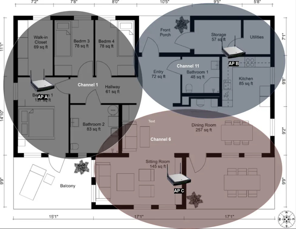 Proper 3-cell channel reuse pattern using non-overlapping channels 1, 6, and 11.
6. Channel Width and DFS Planning
Channel bonding combines multiple 20 MHz channels into 40 MHz, 80 MHz, or 160 MHz blocks. While bonding increases maximum theoretical data rates, it also cuts the number of available independent channels and raises the thermal noise floor by 3 dB for every doubled width.
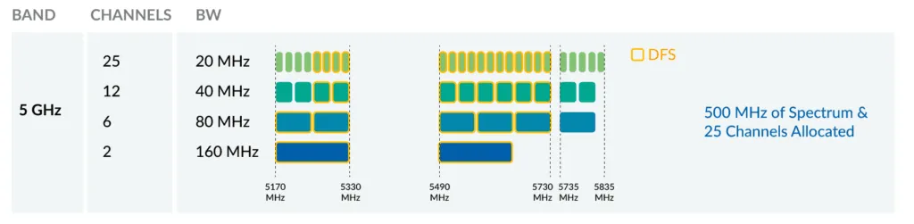 5 GHz channel allocation overview (Source: Fortinet).
- Enterprise & High-Density Deployments: Stick to 20 MHz channels (or selectively 40 MHz in clean 5 GHz environments). This maximizes your non-overlapping channel pool and prevents CCI.
- Dynamic Frequency Selection (DFS): Channels in the UNII-2 and UNII-2 Extended bands share frequencies with radar systems. When an AP detects radar pulses, it must immediately vacate the channel (Channel Availability Check). Avoid DFS channels in outdoor deployments or near airports where radar events will cause service drops.
7. Airtime Efficiency and Minimum Basic Data Rates
Wi-Fi is a shared half-duplex medium. When an access point allows legacy or weak client devices to associate at low data rates (such as 1 Mbps or 6 Mbps), those clients consume massive amounts of airtime to transmit small payloads.
To protect network capacity:
- Disable legacy data rates: Turn off 802.11b rates (1, 2, 5.5, 11 Mbps) entirely.
- Set a minimum basic data rate: Enforcing a minimum rate of 12 Mbps or 24 Mbps forces client devices to modulate faster, trims airtime consumption, and encourages sticky clients to roam to closer APs more aggressively.
8. AP Placement and the Fresnel Zone Dilemma
A classic example of flawed wireless deployment is placing APs in hallways and corridors of hotels or office complexes to simplify installation.
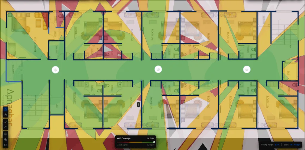 Flawed hallway placement: Signal concentrates in corridors while rooms suffer heavy wall attenuation.
The Fresnel zone is an elliptical volume surrounding the direct line-of-sight path between the transmitter and receiver. For reliable transmission, at least 60% of the first Fresnel zone must remain free of obstructions.
When APs sit in corridors, the signal must pass through thick fire doors, metallic frames, and interior masonry at sharp angles, increasing the effective wall thickness.
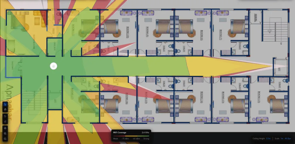 Signal degradation caused by acute incident angles through corridor walls.
The Correct Architectural Solution
Rather than trying to blast signals from hallways, deploy lower-power in-room wall-plate APs or place APs directly inside primary coverage zones.
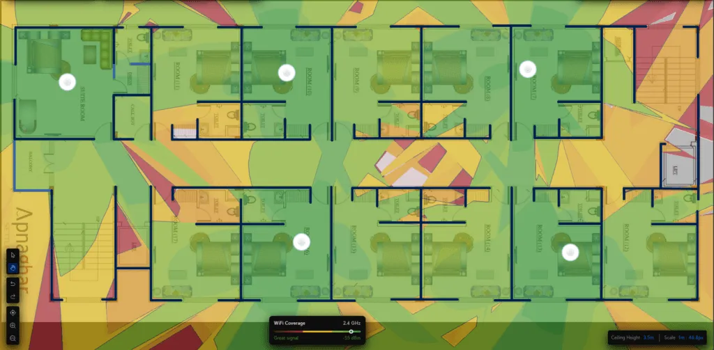 Strategic in-room AP distribution providing consistent -55 dBm to -60 dBm coverage.
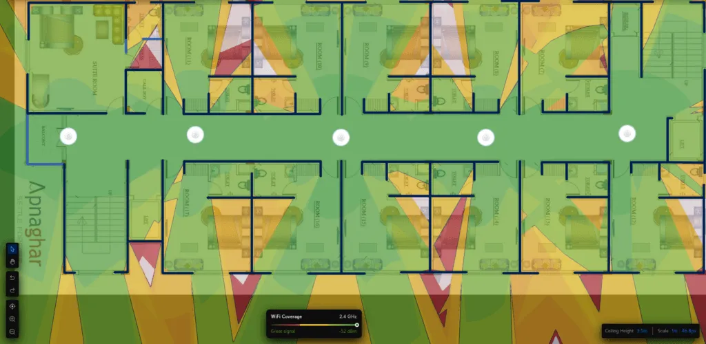 Simulation comparison: Even five high-power APs on a balcony leave interior rooms starved at -75 dBm due to structural attenuation.
Distributing low-power APs directly inside living or working spaces ensures clear line-of-sight, maintains the 60% Fresnel clearance, and allows you to tune transmit power down, minimizing co-channel bleeding into neighboring rooms.
Next Steps in Wireless Engineering
Reliable Wi-Fi design is an exercise in RF hygiene. By designing for the least-capable client, keeping channel widths conservative, enforcing strict non-overlapping channel reuse, and placing APs inside the primary coverage cells, you eliminate the vast majority of wireless performance bottlenecks.
In subsequent lab guides, we will explore deeper enterprise configurations, including 802.1X EAP-TLS authentication with RADIUS, dynamic VLAN steering, and fast BSS transition (802.11r/k/v) roaming optimization.